
Multiple socket having rotatable socket units

a multi-socket, rotatable technology, applied in the direction of flexible/turnable line connectors, electrical discharge lamps, coupling device connections, etc., can solve the problems of occupying excessive space, unable to use, and 2/b> becoming idl

Inactive Publication Date: 2005-02-10
ATOM TECHNOLOGIES
View PDF1 Cites 24 Cited by
  • Summary
  • Abstract
  • Description
  • Claims
  • Application Information

AI Technical Summary

Benefits of technology

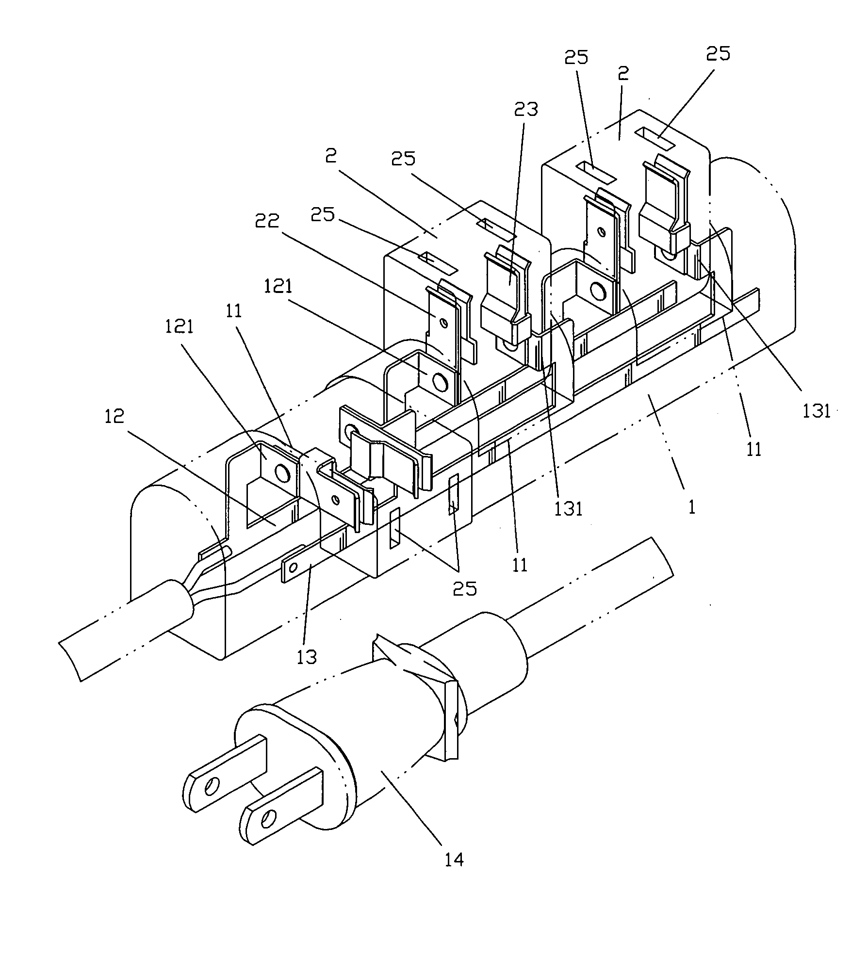
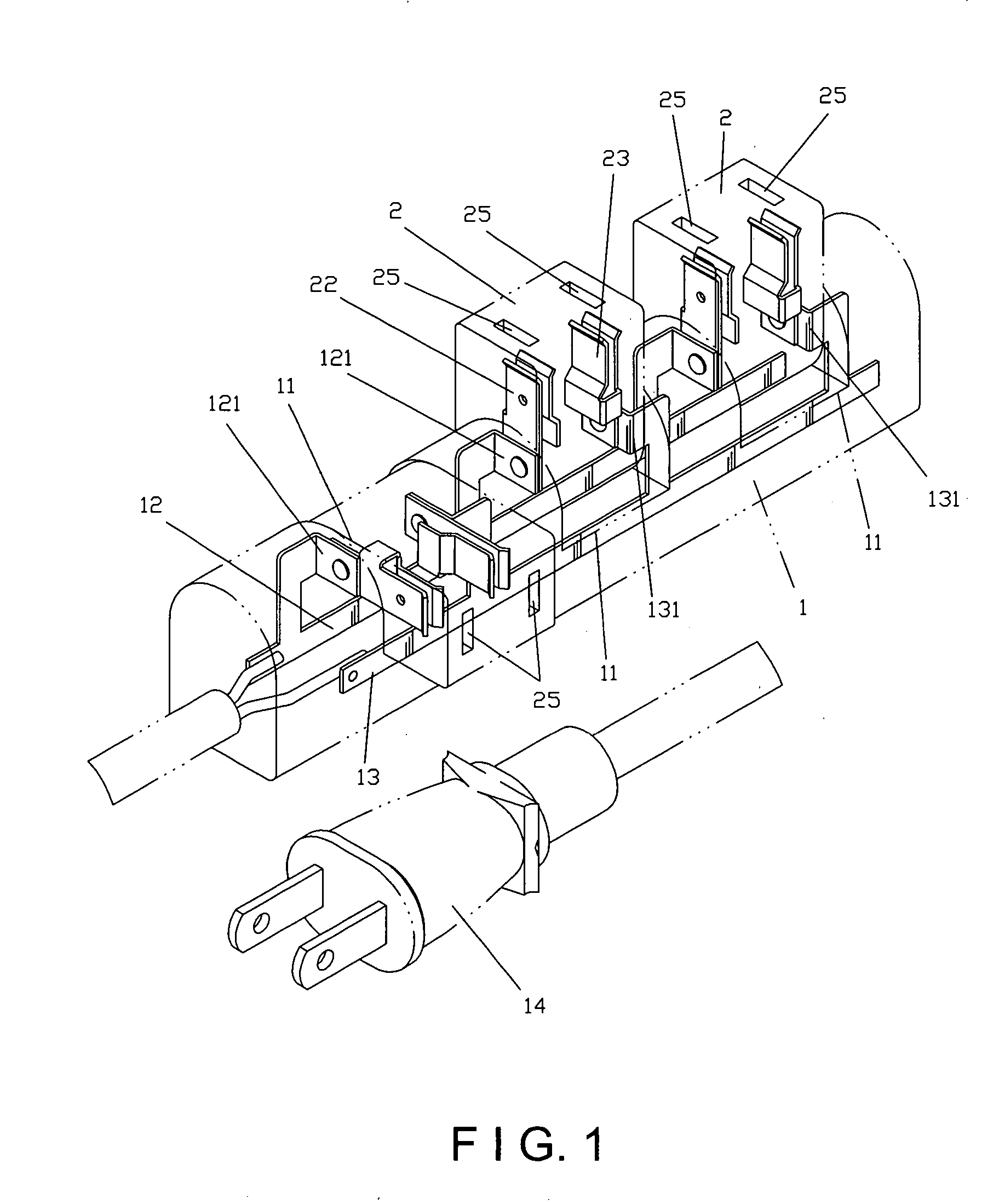
[0005] The primary object of the invention is to provide a multiple socket having rotatable socket units and insertion openings having freely rotated angles, such that when large plugs are inserted at the multiple socket, directions of the socket units can be adjusted as desired without having the plugs blocking insertion openings of adjacent socket units. Consequently, all socket units of the multiple socket can be thoroughly utilized for bringing largest effects of the multiple socket.
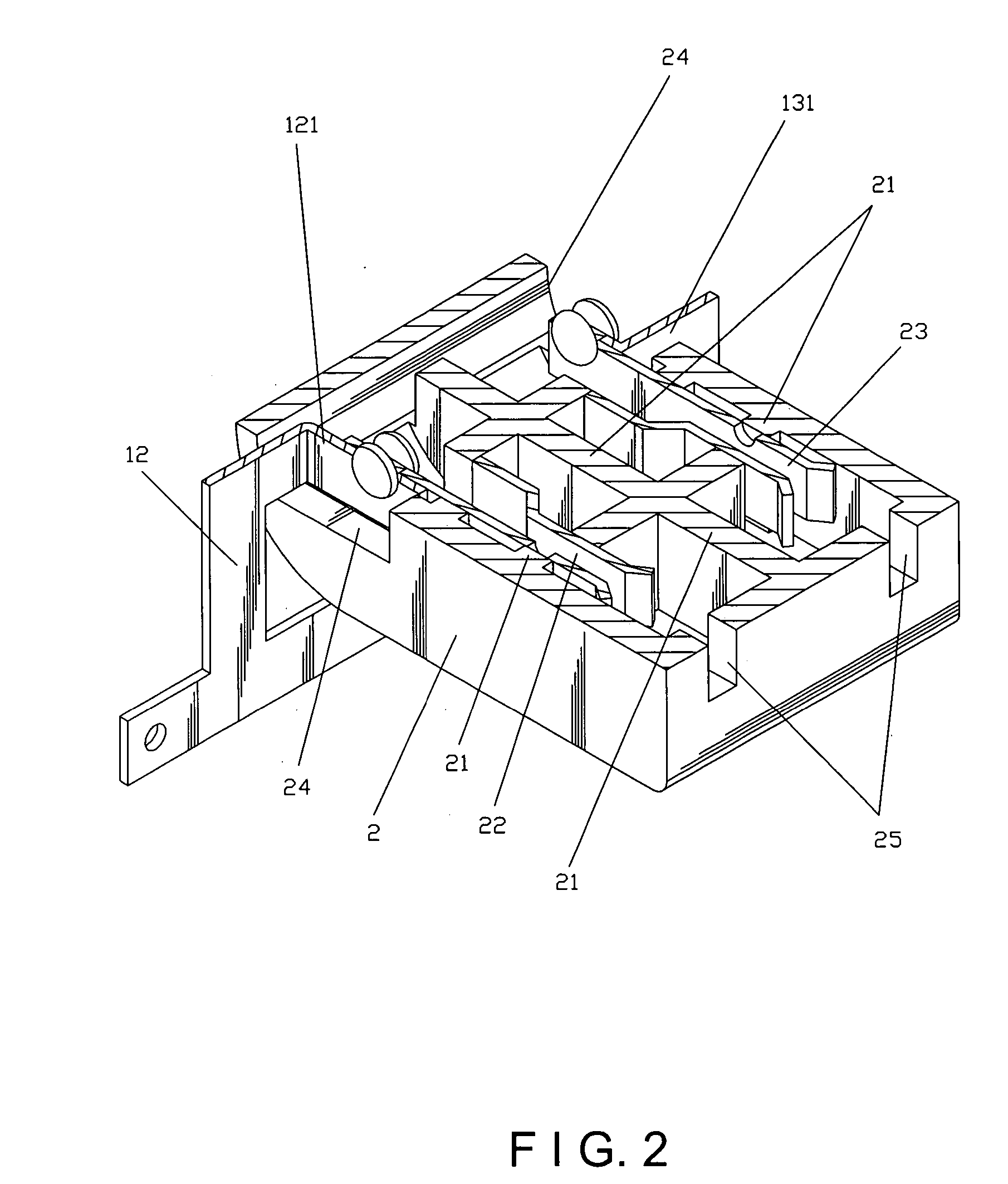
[0006] The multiple socket having rotatable socket units comprises a plurality of pivotally rotatable socket units having spaces in between at a housing. The housing has first and second conducting straps at an interior thereof. The first and second conducting straps are pivotally connected with first and second insertion straps in the socket unit, such that each socket unit is capable of driving the first and second insertion straps and further freely rotating relative to the housing.

Problems solved by technology

However, when the multiple socket is inserted by a plug B having a relatively larger volume (an adaptor plug for instance), the plug B frequently blocks another set of adjacent insertion openings A2, and the set of blocked insertion openings A2 then becomes idle and cannot be used.
Not only production cost is raised, but also inconveniences such as occupying excessive space are resulted.
Therefore, the aforesaid type of multiple socket is hardly ideal when put to practical use.

Method used


Image

  • Multiple socket having rotatable socket units
  • Multiple socket having rotatable socket units
  • Multiple socket having rotatable socket units

Examples


Embodiment Construction

[0015] To better understand the invention, detailed descriptions shall be given with the accompanying drawings hereunder.

[0016] Referring to FIGS. 1 and 2 showing an embodiment according to the invention, all socket units of the multiple socket are disposed in a rotatable arrangement. The embodiment according to the invention comprises a housing 1 and a plurality of socket units 2.

[0017] The housing 1 has a plurality of notches 11, and a first conducting strap 12 and a second conducting strap 13 transversely disposed at an interior thereof. The first conducting strap 12 is a live wire, and the second conducting strap 13 is a ground wire. The first and second conducting straps 12 and 13 respectively have projecting pivotal ends 121 and 131 for corresponding with positions of the notches 11. End portions of the first and second conducting straps 12 and 13 are connected to a same power line, which has the other end thereof as a power plug 14.

[0018] The socket units 2 are provided in...


PUM


Abstract

A multiple socket having rotatable socket units includes pivotally rotatable socket units at a housing. The housing has first and second conducting straps at an interior thereof. The first and second conducting straps are pivotally connected with first and second insertion straps in each socket unit. The socket unit is capable of driving the first and second insertion straps for further freely rotating relative to the housing. Using the above structure, the socket units are capable of adjusting directions thereof, thereby avoiding plugs from blocking insertion openings of adjacent socket units.

Description

BACKGROUND OF THE INVENTION [0001] (a) Field of the Invention [0002] The invention relates to a multiple socket having rotatable socket units, and more particularly, to a multiple socket having rotatable socket units with each socket unit being capable of driving first and second conducting straps for further freely rotating relative to a housing thereof, thereby enabling electric appliance plugs having various sizes to be independent inserted with different angles. [0003] (b) Description of the Prior Art [0004] Referring to FIG. 7 showing a common multiple socket, the prior multiple socket has a plurality of sets of insertion openings A2 at a housing A1 thereof. The insertion openings A2 are disposed with equal distances in between, and the distances allow insertions of small-sized plugs without having the plugs interfering with one another. However, when the multiple socket is inserted by a plug B having a relatively larger volume (an adaptor plug for instance), the plug B frequen...

Claims


Application Information

Patent Timeline
Patent Type & Authority Applications(United States)
IPC IPC(8): H01R13/70H01R13/717H01R25/00H01R35/04
CPCH01R13/701H01R35/04H01R25/003
Inventor HUANG, CHYONG-YEN
Owner ATOM TECHNOLOGIES
Learn More