Retractable lanyard systems, anchoring brackets for retractable lanyards and methods of anchoring retractable lanyards

a retractable lanyard and bracket technology, applied in the field of retractable lanyard systems, self-retracting or retractable lanyard systems, to anchoring brackets for retractable lanyards, methods of anchoring retractable lanyards, etc., can solve the problems of excessive wear of the line constituent of the retractable lanyard, and the inability to operate the retractable lanyard

Inactive Publication Date: 2005-02-17
SPERIAN FALL PROTECTION
View PDF6 Cites 27 Cited by
  • Summary
  • Abstract
  • Description
  • Claims
  • Application Information

AI Technical Summary

Benefits of technology

[0006] In one embodiment, the retractable lanyard is removable from the cradle. Preferably, the first axis and the second axis pass sufficiently close to the center of gravity of the retractable lanyard to allow the bracket to orient the retractable lanyard generally in the direction of the lifeline exiting the housing of the retractable lanyard under the force applied by the lifeline to the housing of the retractable lanyard. Given the typical size of retractable lanyard, the pivot point of the second axis is preferably within approximately one inch of the center of gravity of the retractable lanyard. In one embodiment, as used in connection with the MILLER MIGHTYLITE® self-retracting lifeline, available from Bacou-Dalloz Fall Protection of Franklin, Pa., for example, the second axis (or the pivot point of the bracket) was about 0.7 inches above the center of gravity of the retractable lanyard. Preferably, the pivot point lies slightly above the center of gravity so that the retractable lanyard remains upright when not in use, although this is a convenience and not a requirement. The retractable lanyard system can further comprising a retractable lanyard.

Problems solved by technology

The horizontal component thereby created can lead to improper operation of the retractable lanyard.
In that regard, binding of the lanyard can occur at the outlet of the retractable lanyard causing excessive wear to the line constituent of the retractable lanyard.

Method used


Image

  • Retractable lanyard systems, anchoring brackets for retractable lanyards and methods of anchoring retractable lanyards
  • Retractable lanyard systems, anchoring brackets for retractable lanyards and methods of anchoring retractable lanyards
  • Retractable lanyard systems, anchoring brackets for retractable lanyards and methods of anchoring retractable lanyards

Examples


Embodiment Construction

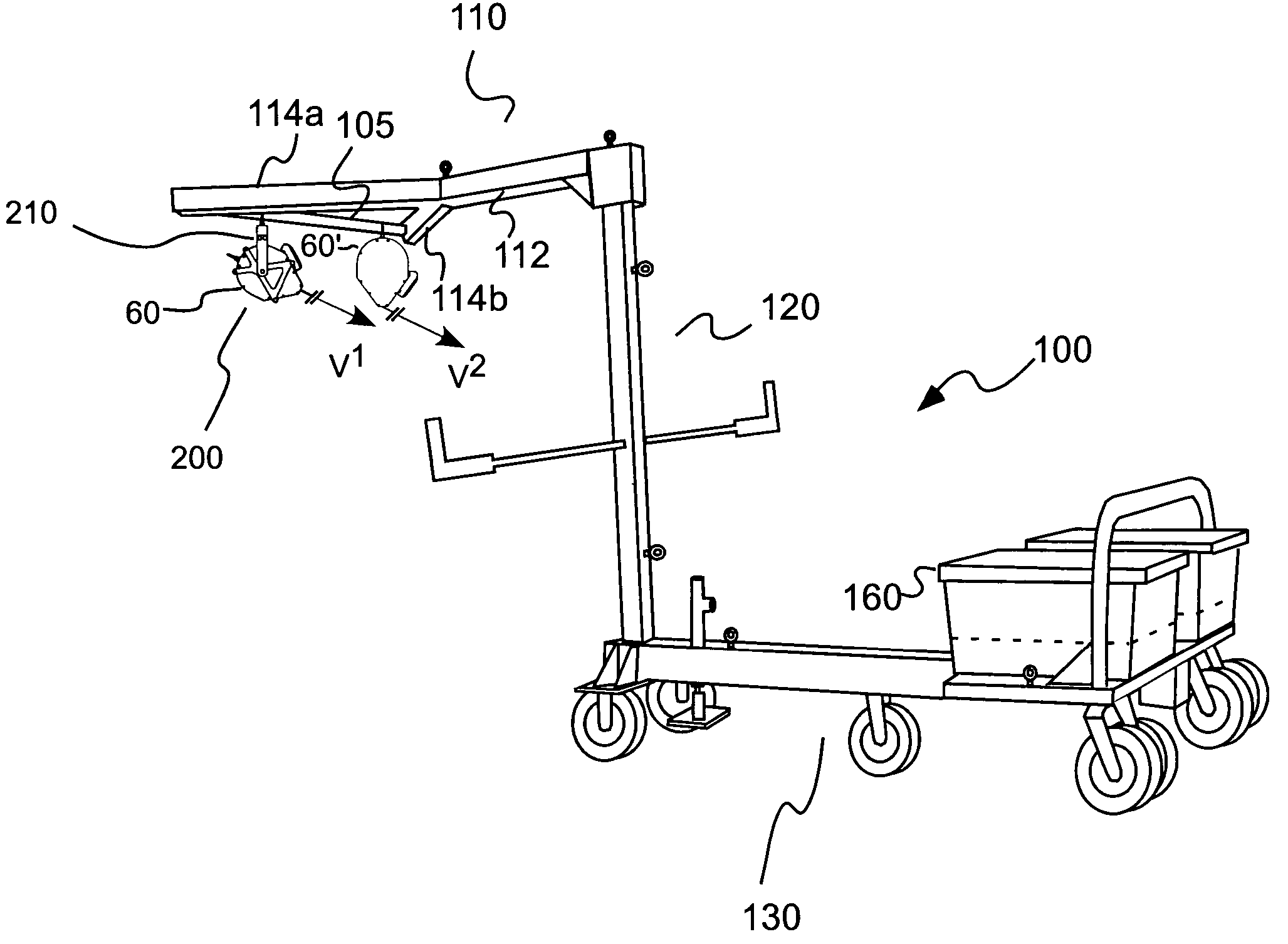
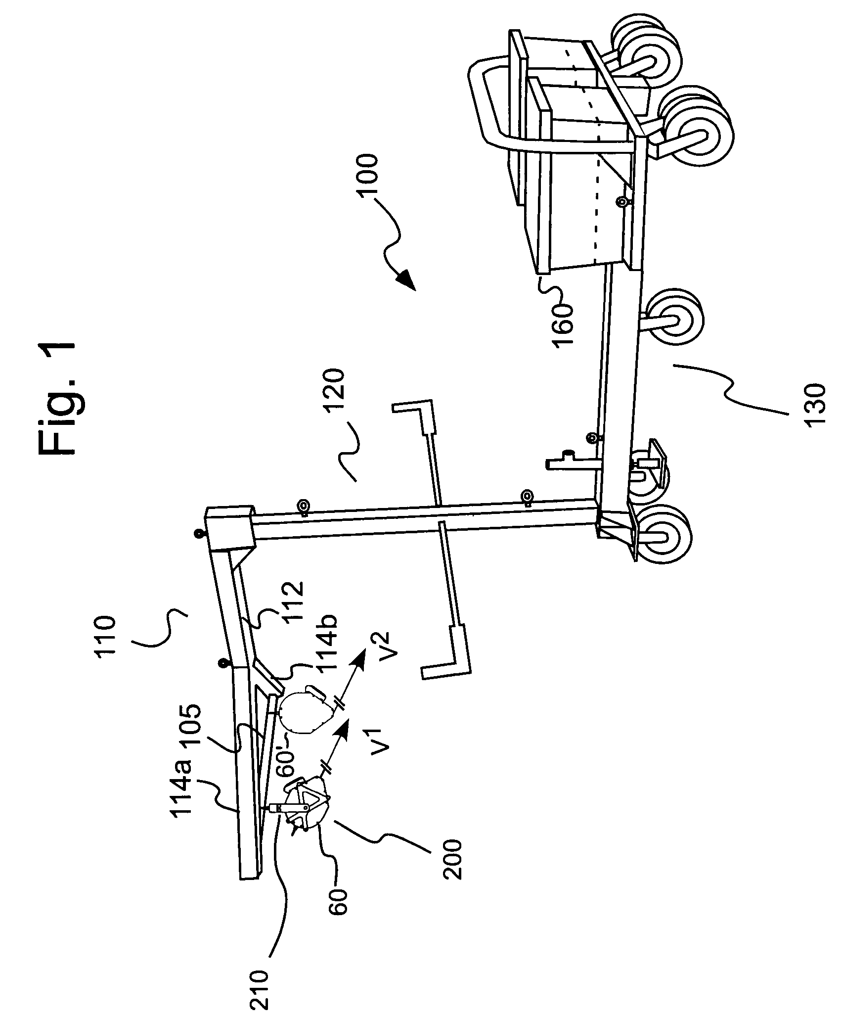
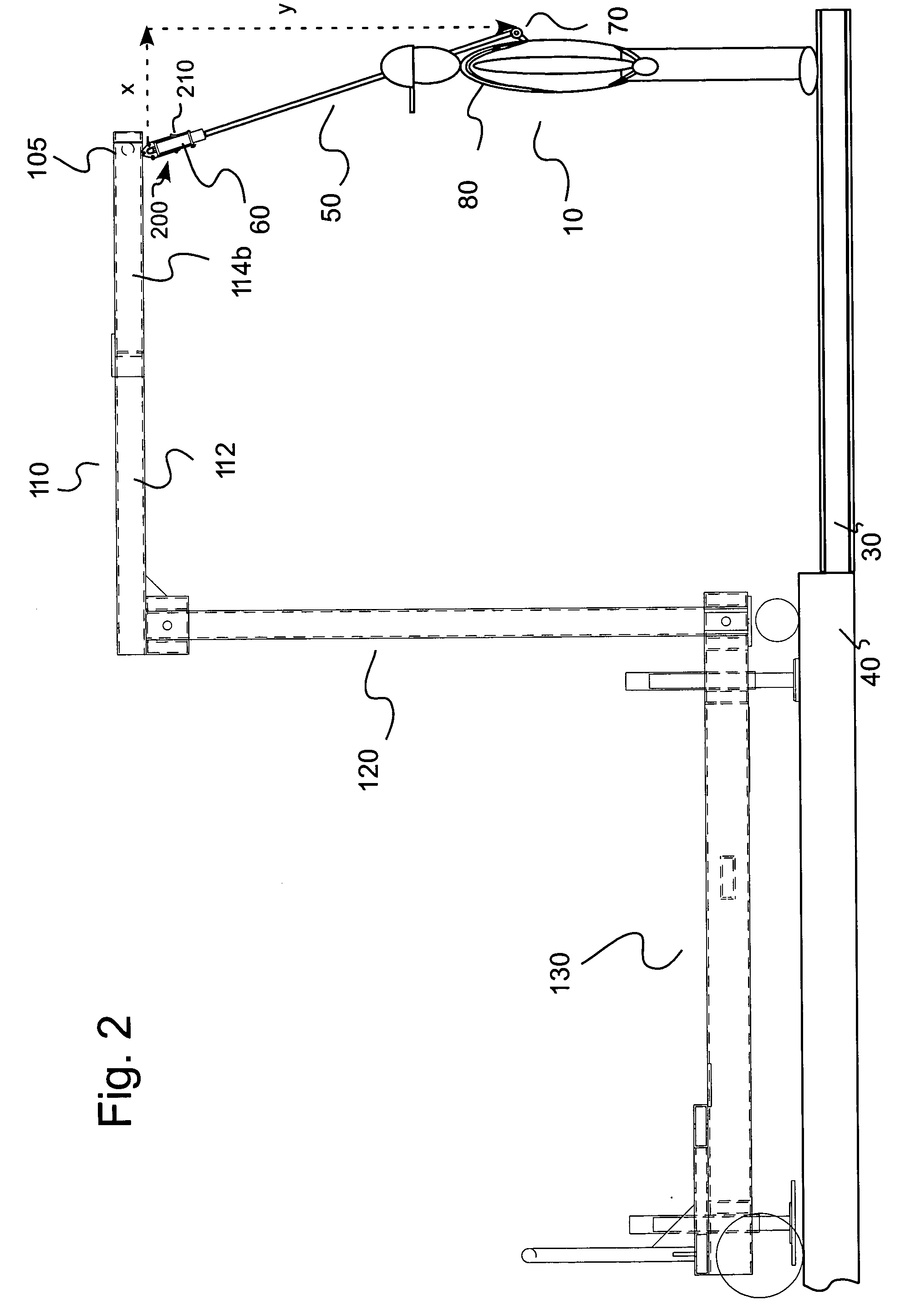
[0022] In general, the retractable lanyard systems of the present invention can incorporate commercially available retractable lanyards therein. In several embodiments of the present invention, such commercially available lanyards need not be retrofitted or changed in any manner for use in the systems of the present invention. An example of a commercially available, retractable lanyard suitable for use in the present invention is the MILLER MIGHTYLITE® self-retracting lifeline, available from Bacou-Dalloz Fall Protection of Franklin, Pa. See also, for example, U.S. Pat. No. 5,771,993, assigned to the assignee of the present invention, the disclosure of which is incorporated herein by reference, for an example of a retractable lanyard system.

[0023] As described, for example, in U.S. Pat. No. 5,771,993, retractable lanyards such as retractable lanyard 60 typically include a housing 61 incorporating a breaking mechanism 62 (see, for example, FIG. 3D) to arrest the fall of a mass or pe...


PUM


Abstract

An anchoring system includes an anchor member to anchor the lifeline and at least one extending unit to extend the anchor member out to a working position beyond (horizontally) and above (vertically) an edge to provide for an overhead anchoring point. The anchoring system preferably further includes a support to which the extending unit is attached. The support immobilizes the overhead anchoring system so that the anchor member remains at the working position (even in the case of a fall by the worker). A method of anchoring a fall protection lifeline for use by a worker working at or beyond an edge includes the steps: elevating an anchor member to position the lifeline above the head of a worker and supporting the anchor member at the working position. The method can also include the step of extending the anchor member to a working position horizontally beyond and above the edge.

Description

BACKGROUND OF THE INVENTION [0001] The present invention relates to self-retracting or retractable lanyard systems, to anchoring brackets for retractable lanyards and to methods of anchoring retractable lanyards, and, especially, to retractable lanyards, to anchoring brackets for retractable lanyards and to methods of anchoring retractable lanyards that facilitate movement of a user of a retractable lanyard to positions not directly vertically under the anchor point of the retractable lanyard. [0002] Fall protection systems including safety harnesses and lanyards such as self-retracting or retractable lanyards are commonly used to protect persons subjected to the potential of a fall from a height. Often, a lifeline or lanyard is connected to an overhead anchorage point on a structure directly over the user. However, in many cases the anchor point and the worker's position result in a horizontal component to the vector corresponding to the line between the anchor point and point at w...

Claims


Application Information

Patent Timeline
Patent Type & Authority Applications(United States)
IPC IPC(8): A62B1/04A62B1/08A62B1/10A62B1/16E04G21/32
CPCA62B1/04E04G21/3261A62B35/0068E04G21/3276E04G21/3238
Inventor ANDERSON, PRESTON L.
Owner SPERIAN FALL PROTECTION
Why Eureka
Try Eureka