Rigid rail fall protection apparatus having bypassable moveable anchorages

a technology of moving anchorage and rigid rails, which is applied in the field of rigid rail fall protection apparatuses, can solve problems such as unimpeded manner, and achieve the effect of simple and less costly construction and installation

Active Publication Date: 2011-08-09
10739987 CANADA LTD
View PDF19 Cites 28 Cited by
  • Summary
  • Abstract
  • Description
  • Claims
  • Application Information

AI Technical Summary

Benefits of technology

[0009]The fall protection apparatus of the present invention provides a single substantially horizontally and longitudinally extending rigid rail onto which two laterally spaced apart moveable anchorages are mounted. Each moveable anchorage is adapted to be independently movable along the length of the rail, with the anchorages being permitted to freely bypass one another therealong. Advantageously, two workers attached to separate anchorages can use the fall protection apparatus and pass by each other in an unimpeded manner. Further, as the fall protection apparatus requires only a single rigid rail and associated support system to accomplish this, the rail is simpler and less costly to construct and install than prior art dual rail systems.
[0012]As the connecting member extends substantially continuously along the length of the track, the propensity for torsional buckling of the rail when in use is greatly reduced or eliminated, particularly if the connecting member is of sufficient stiffness. The rail also preferably includes stops at either end for arresting movement of the anchorages to prevent the moveable anchorages from falling off the ends.

Problems solved by technology

Advantageously, two workers attached to separate anchorages can use the fall protection apparatus and pass by each other in an unimpeded manner.

Method used


Image

  • Rigid rail fall protection apparatus having bypassable moveable anchorages
  • Rigid rail fall protection apparatus having bypassable moveable anchorages
  • Rigid rail fall protection apparatus having bypassable moveable anchorages

Examples


Embodiment Construction

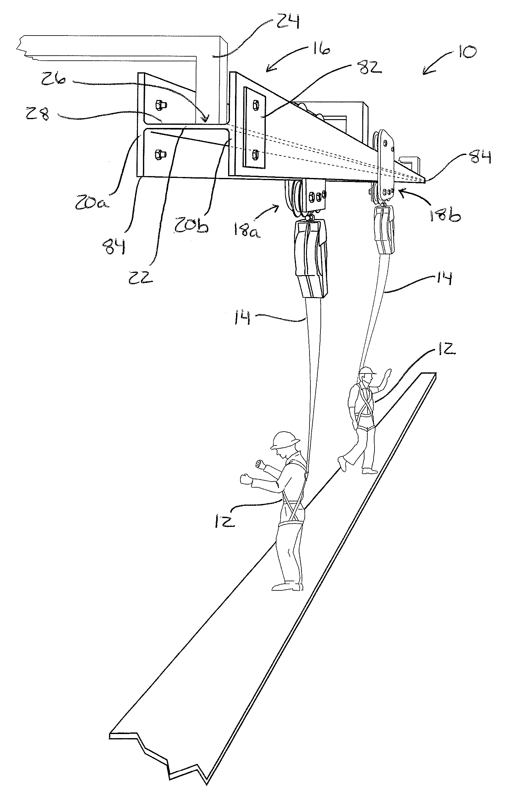
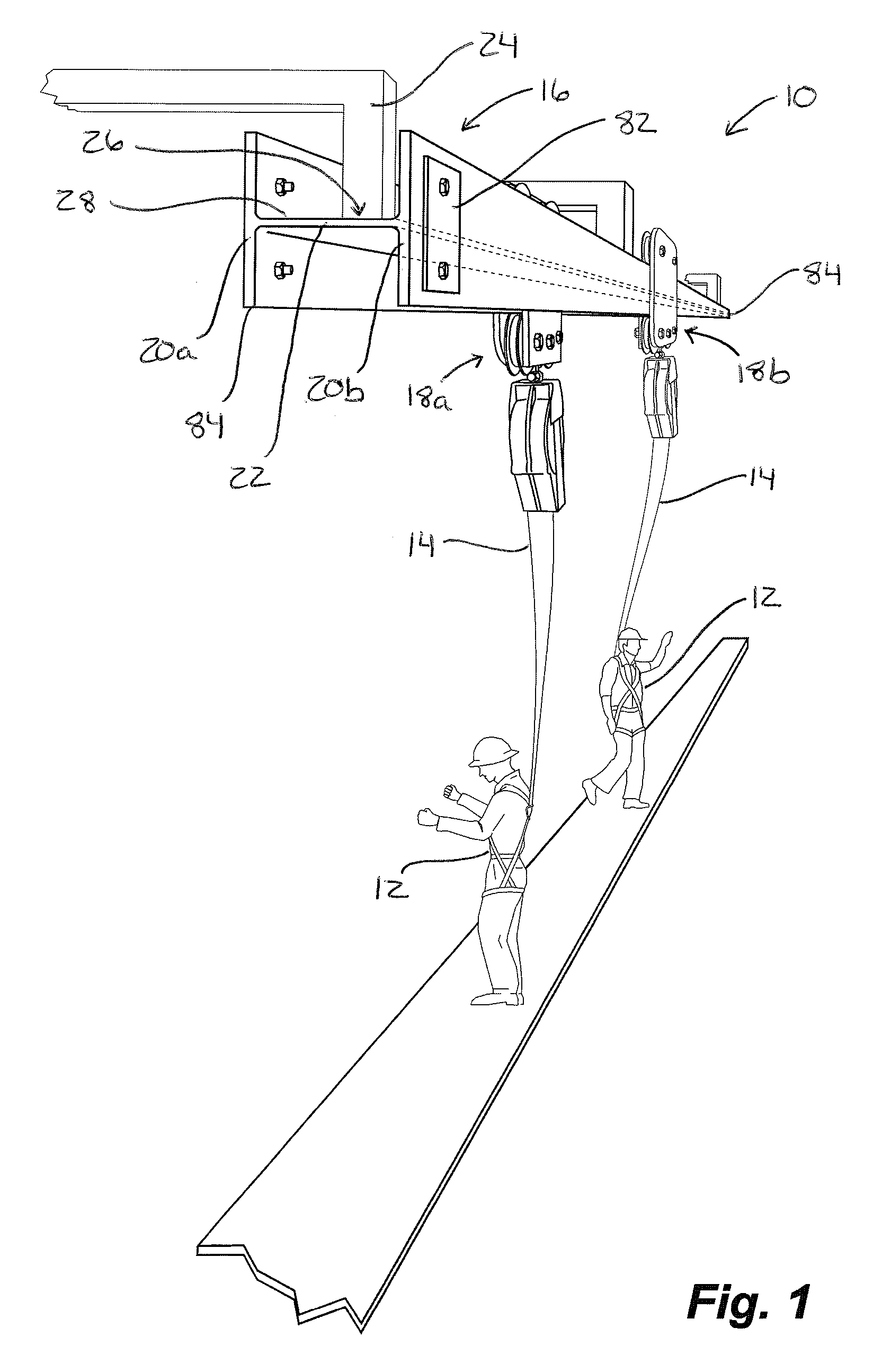
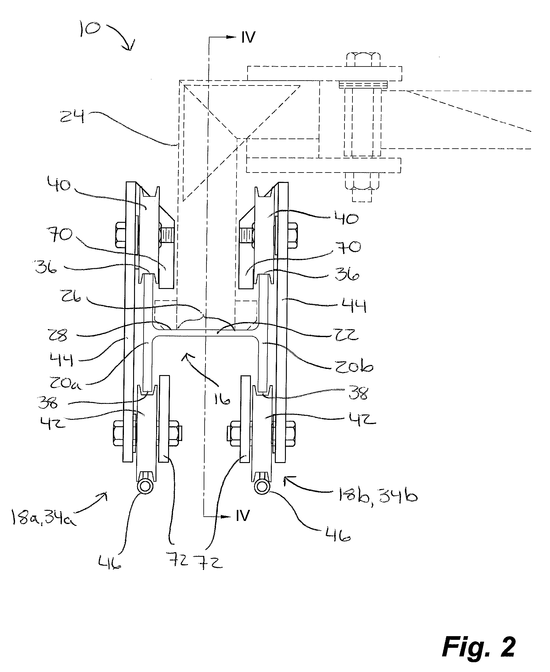
[0024]With reference to FIG. 1, an embodiment of a fall protection apparatus 10 is shown installed on an overhead structure and in use with two workers 12, each attached to the fall protection apparatus 10 by a lanyard 14, with a self retracting lanyard being shown. With further reference to FIG. 2, the fall protection apparatus 10 generally comprises a substantially horizontally and longitudinally extending rigid rail 16 having a generally H-shaped cross-section and first and second moveable anchorages 18a, 18b attached to each of the rail 16 and a lanyard 14. More particularly, the rigid rail 16 comprises opposing substantially vertically oriented first and second longitudinally extending flanges or tracks 20a, 20b and a horizontally oriented web or connecting member 22 extending between the tracks 20a, 20b and attached thereto. The moveable anchorages 18a, 18b are mounted on the first and second tracks 20a, 20b, respectively. The first and second flanges 20a, 20b support forces f...


PUM


Abstract

A fall protection apparatus includes a single longitudinally extending rigid rail onto which two laterally spaced apart moveable lanyard anchorages are mounted. The rail has a generally H-shaped cross-section with opposing vertically oriented first and second tracks laterally spaced apart by a connecting member extending between the tracks and substantially continuously along the length of the tracks The apparatus is attached to a structure by a support member, such as an overhead or lower support member, with the support member being attached to an upper or lower surface of the connecting member respectively. Each anchorage is adapted to be independently moveable along the length of one of the tracks, with the tracks being sufficiently spaced apart to permit the anchorages to freely pass by each other and the attachment point.

Description

FIELD OF THE INVENTION[0001]The invention relates to fall protection apparatus and in particular to a fall protection apparatus of the type having a rigid rail with moveable anchorages to permit a worker to move along a length of a work area.BACKGROUND OF THE INVENTION[0002]Many work situations require workers to be positioned on top of platforms or vehicles that cannot be practically protected by a guardrail system enclosing the work area. To prevent the workers from falling from such elevated positions and thereby sustaining serious or mortal injuries, various fall protection systems can be used. In general, fall arrest or fall protection systems are designed to prevent the worker from reaching an unprotected edge or to quickly stop a fall before the worker impacts a lower level. Such systems typically include an anchorage secured to a structure overhead the work area, a safety harness worn by the worker, and a flexible tether line or “lanyard” interconnecting the anchorage to the...

Claims


Application Information

Patent Timeline
Patent Type & Authority Patents(United States)
IPC IPC(8): A62B35/00
CPCA62B35/0087E04G21/3261E04G21/3295
Inventor SMALL, GREG
Owner 10739987 CANADA LTD
Why Eureka
Try Eureka