
Trailer skirt panel

a skirt panel and trailer technology, applied in the field of skirt panels, can solve the problems of limited progress made with heavy-duty vehicles, high fuel consumption of such vehicles, and major concern of fuel consumption, and achieve the effect of reducing the aerodynamic drag, and reducing the maximum aerodynamic drag

Active Publication Date: 2009-08-25
ZF COMPOSITES NORTH AMERICA LTD
View PDF22 Cites 146 Cited by
  • Summary
  • Abstract
  • Description
  • Claims
  • Application Information

AI Technical Summary

Benefits of technology

"The present invention provides a skirt panel for attachment beneath a trailer of a tractor-trailer rig, which includes optional rear wheel bogeys. The skirt panel is made of a monolithic composite thermoplastic / metal reinforcing structure, with longitudinally-extending forward and rearward sections connected by a curved section. The skirt panel is designed to reduce aerodynamic drag and improve fuel efficiency of the trailer. The skirt panel is secured to the trailer using bracket means and is made of a thermoplastic material co-extruded with a styrene acrylic elastomer. The skirt panel can also include a synthetic plastic component for flexing over road objects. The patent text also describes a method for vacuum forming the skirt panel. The skirt panel helps to improve the efficiency of the trailer and reduce the aerodynamic drag."

Problems solved by technology

Modern cars are quite aerodynamically efficient but limited progress has been made with heavy-duty vehicles, trucks and the like.
This is unfortunate principally because the fuel consumption by such a vehicle is high and any improvement in its aerodynamics performance is of great significance to transportation tractor-trailer rigs of the transportation industry in improving fuel economy.
However fuel consumption is a major concern.
It has recently been suggested that higher fuel prices, coupled with intense competition, may have the effect of closing down certain carriers.
As the trailer of a large tractor-trailer rig is pulled forward by the tractor, a great deal of turbulence is created along the side and underneath the trailer as the vehicle disturbs the air.
This turbulence results in increased resistance to forward movement of the tractor-trailer rigs, and thus to lower fuel efficiency.
A large problem is the energy needed to overcome wind resistance.
This interference creates turbulence and a high aerodynamic drag, which results in high fuel use and a high cost of operation.
Furthermore, the turbulent flow can affect the trailers ability to track behind the trailer.
This reduced driving stability is most prevalent in high crosswind conditions or when the trailer is empty.
Furthermore, the turbulent flow, caused by yaw angle air traveling across the trailer bottom and releasing from the downwind side, creates a hazard for the drivers of other vehicles when it is raining or snowing, or the roadway is wet, for in such a situation, the rain or snow and any water splashed up from the roadway by the tires swirls around the tires and is thrown outwardly by the tires themselves and by the turbulent air flow.
When this splashing and spraying water strikes the windshields of other vehicles, it lowers visibility for such motorists, and can cause them to lose control of their vehicles.
Further, the spray raised by the rear tires reduces the truck driver's vision of the rear of the truck, making it more difficult for the truck driver to handle his vehicle when it's moving in traffic it is therefore advisable to improve the visibility of the driver.
A major disadvantage of tractor trailers on the highway is that, unaltered, the turbulent air flow beneath and behind a tractor trailer is generally in a direction transverse to that of the movement of the tractor trailer.
This means that in wet or snowy conditions, mist and / or snow is thrown laterally of the trailer causing a vision and turbulence problem for any motorist passing or being passed by the tractor-trailer rig.
Each of the above patented devices, though providing improvements in the art, have failed to adequately provide an aerodynamic side panel structure which presented a durable and easy to use fixed structure for accomplishing airflow improvement around a tractor-trailer truck.
Some disclosed structures used very rigid side panels, which were difficult to maintain in position, and were awkward to handle.
Some structures required cumbersome tensioning means to maintain the skirt or deflector in position.

Method used


Image

  • Trailer skirt panel
  • Trailer skirt panel
  • Trailer skirt panel

Examples


Embodiment Construction

Description of FIGS. 1, 1A and 2

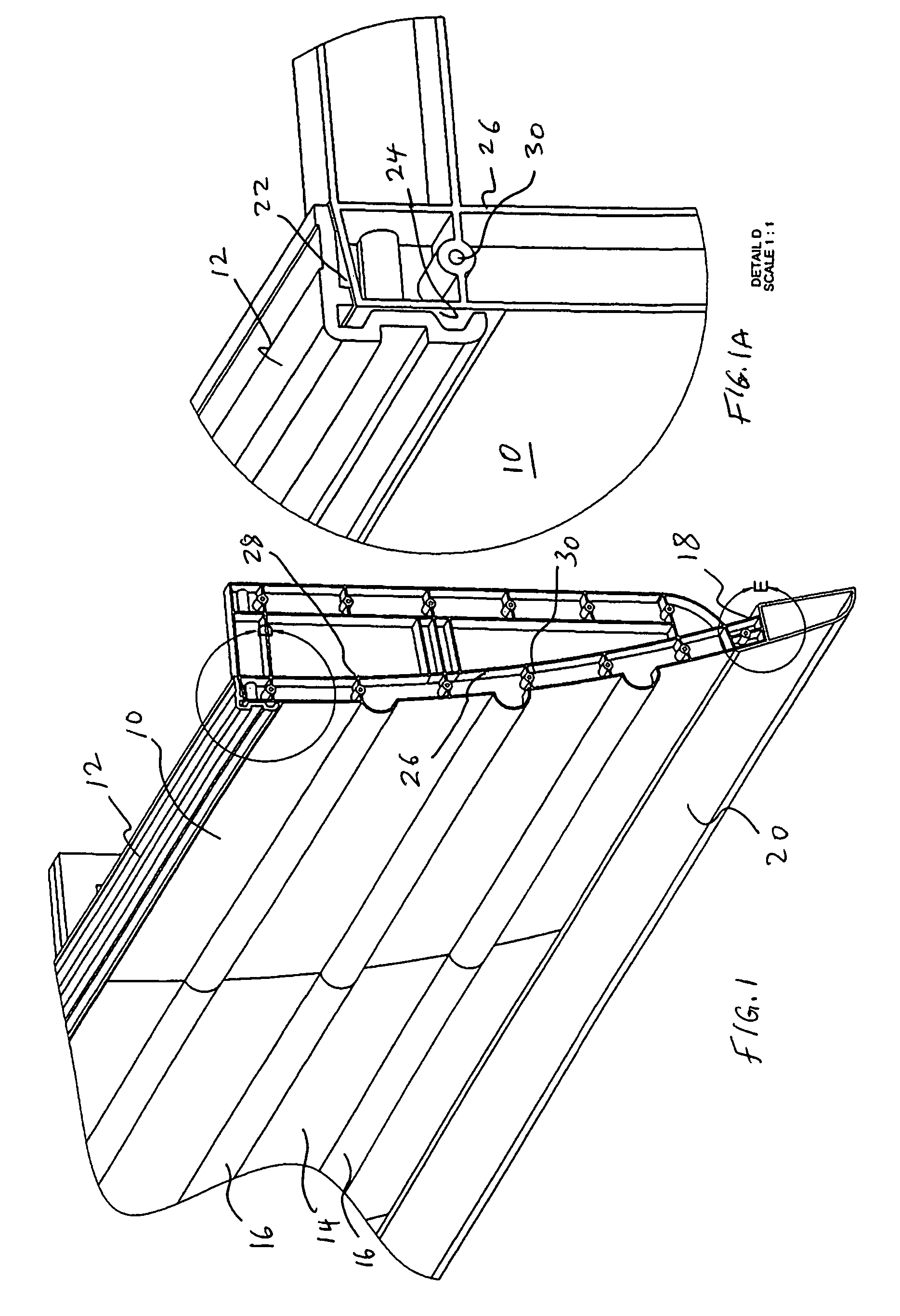
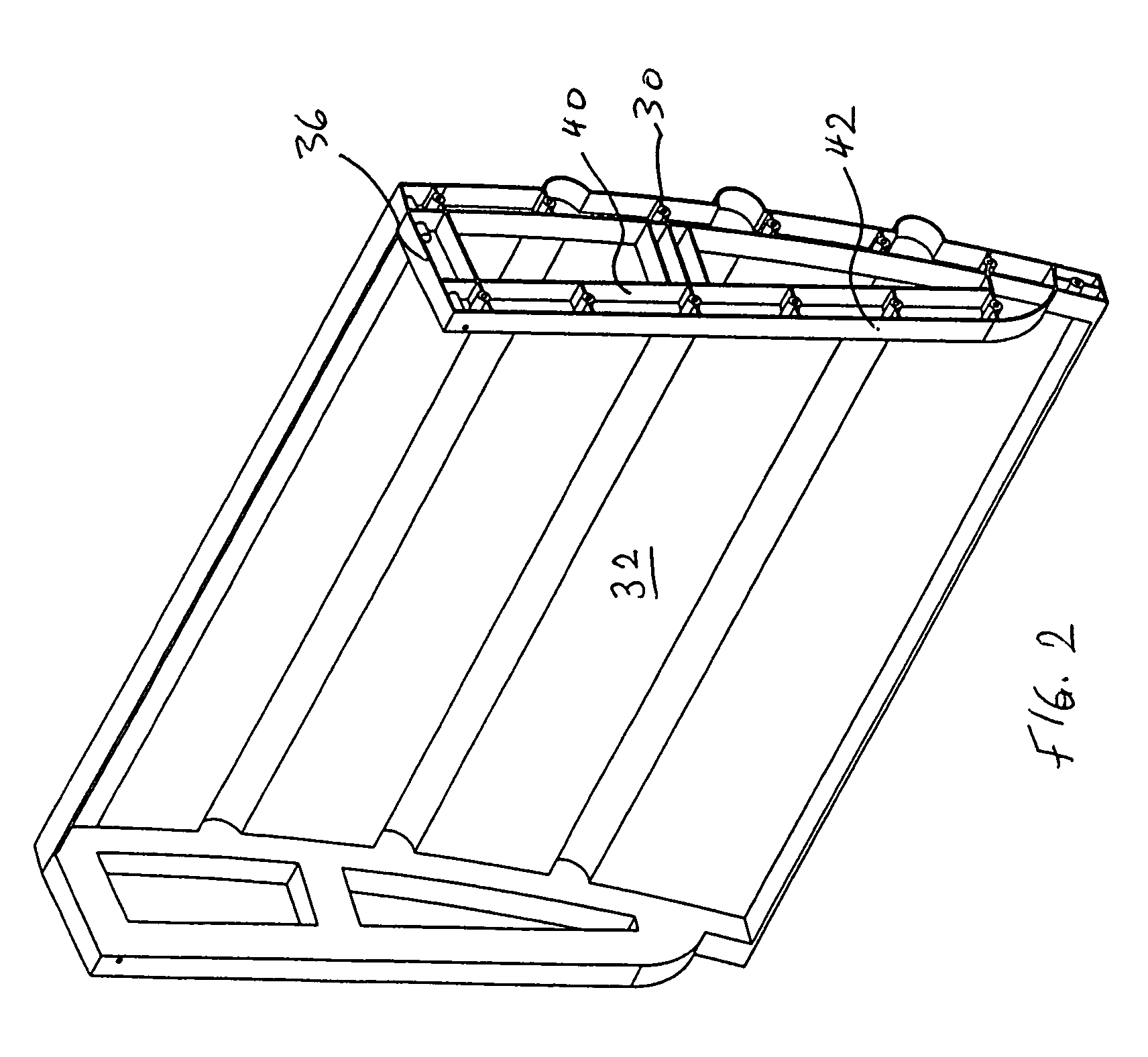
[0099]As seen in FIGS. 1, 1A and 2, the skirt panel 10 is a generally rectangular flat piece of thin thermoplastic material, e.g., ABS (acrylic / butadiene / styrene resin) with a separate extruded but secured, as by thermoplastic fusion, LURAN or CENTREX UV-resistant cap 12. The exterior face 14 of the skirt panel 10 is formed with integral, spaced-apart, horizontal arcuate protrusions 16. The lower edge 18 of the skirt panel 10 has secured thereto by any suitable means, e.g., by a Plastite screw combination, a monolithic base of an extruded, flexible lower panel component 20 of e.g., SANTOPRENE or PVC. As previously described, this allows flexing of the final skirt panel 10 over road objects (e.g., curbs, rail road tracks and below grade loading docks).

[0100]As seen in FIG. 1A, the cap extrusion 12 is suitably secured to the top edge 22 and the top face 24 of the skirt panel 10 in any suitable manner, e.g., by thermoplastic fusion. The exterior facing e...


PUM


Abstract

A skirt panel is provided herein for interconnection to another abutted similar skirt panel for attachment beneath a lower, outer longitudinally-extending edge of a trailer including a rear wheel assembly of a tractor-trailer rig, thereby to provide a continuous fairing extending downwardly from the trailer. The skirt panel includes a monolithic, generally-rectangular composite reinforced thermoplastic structure, having vertical lateral side edges configured and arranged for connection to associated vertical lateral side edges of abutting similar skirt panels. This provides a longitudinally-extending fairing for extending contiguously on each side of the trailer, a front face of the thermoplastic structure being provided with a plurality of longitudinally-extending, vertically-spaced-apart arcuate protrusions. The outer face of the thermoplastic panel preferably also is provided with dimples. The reinforcing comprising a panel secured to an inner face of the skirt panel and is provided with laterally-extending means whereby abutting skirt panels are secured to one another; whereby, when said fairing is secured to a lower portion of said trailer, the fairing extends downwardly from the trailer to from 60% to 80% of the distance to the road, so that a portion of any impinging air is directed laterally around the wheels of the rear wheel bogeys to reduce the aerodynamic drag of the trailer and of the wheel assembly.

Description

BACKGROUND OF THE INVENTION[0001]1. Field of the Invention[0002]This invention relates to a skirt fairing, which is attachable beneath a lower, longitudinal edge of a trailer, and to methods for the production thereof. The present invention also relates to increased fuel efficiency and greater driving safety by deflecting and otherwise altering the airflow e.g., by creating laminar flow along the side and underneath the trailer of a tractor trailer rig or the like.[0003]2. Description of the Prior Art[0004]Modern cars are quite aerodynamically efficient but limited progress has been made with heavy-duty vehicles, trucks and the like. This is unfortunate principally because the fuel consumption by such a vehicle is high and any improvement in its aerodynamics performance is of great significance to transportation tractor-trailer rigs of the transportation industry in improving fuel economy. Acceleration and speed are, in general, of little interest in trucking. Existing performance i...

Claims


Application Information

Patent Timeline
Patent Type & Authority Patents(United States)
IPC IPC(8): B60J1/00
CPCB62D35/001
Inventor LAYFIELD, BRIANMANCINA, JOSEPHHAWS, JAMESPROKUDIN, ANDRIY
Owner ZF COMPOSITES NORTH AMERICA LTD
Learn More