Modern cars are quite aerodynamically efficient but limited progress has been made with heavy-duty vehicles, trucks and the like.
This is unfortunate principally because the fuel consumption by such a vehicle is high and any improvement in its
aerodynamics performance is of great significance to transportation tractor-trailer rigs of the
transportation industry in improving fuel economy.
However fuel consumption is a major concern.
It has recently been suggested that higher fuel prices, coupled with intense competition, may have the effect of closing down certain carriers.
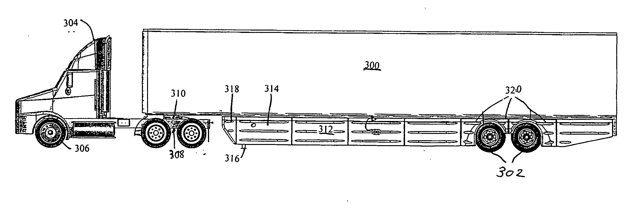
As the trailer of a large tractor-trailer rig is pulled forward by the tractor, a great deal of turbulence is created along the side and underneath the trailer as the vehicle disturbs the air.
This turbulence results in increased resistance to forward movement of the tractor-trailer rigs, and thus to lower
fuel efficiency.
A large problem is the energy needed to overcome wind resistance.
This interference creates turbulence and a high
aerodynamic drag, which results in high fuel use and a high cost of operation.
Furthermore, the turbulent flow can affect the trailers ability to track behind the trailer.
This reduced driving stability is most prevalent in high
crosswind conditions or when the trailer is empty.
Furthermore, the turbulent flow, caused by
yaw angle air traveling across the trailer bottom and releasing from the downwind side, creates a
hazard for the drivers of other vehicles when it is raining or snowing, or the roadway is wet, for in such a situation, the rain or
snow and any water splashed up from the roadway by the tires swirls around the tires and is thrown outwardly by the tires themselves and by the turbulent air flow.
When this splashing and spraying water strikes the windshields of other vehicles, it lowers
visibility for such motorists, and can cause them to lose control of their vehicles.
Further, the spray raised by the rear tires reduces the
truck driver's vision of the rear of the
truck, making it more difficult for the
truck driver to
handle his vehicle when it's moving in traffic it is therefore advisable to improve the
visibility of the driver.
A major
disadvantage of tractor trailers on the highway is that, unaltered, the turbulent air flow beneath and behind a
tractor trailer is generally in a direction transverse to that of the movement of the
tractor trailer.
This means that in wet or snowy conditions, mist and / or
snow is thrown laterally of the trailer causing a vision and turbulence problem for any motorist passing or being passed by the tractor-trailer rig.
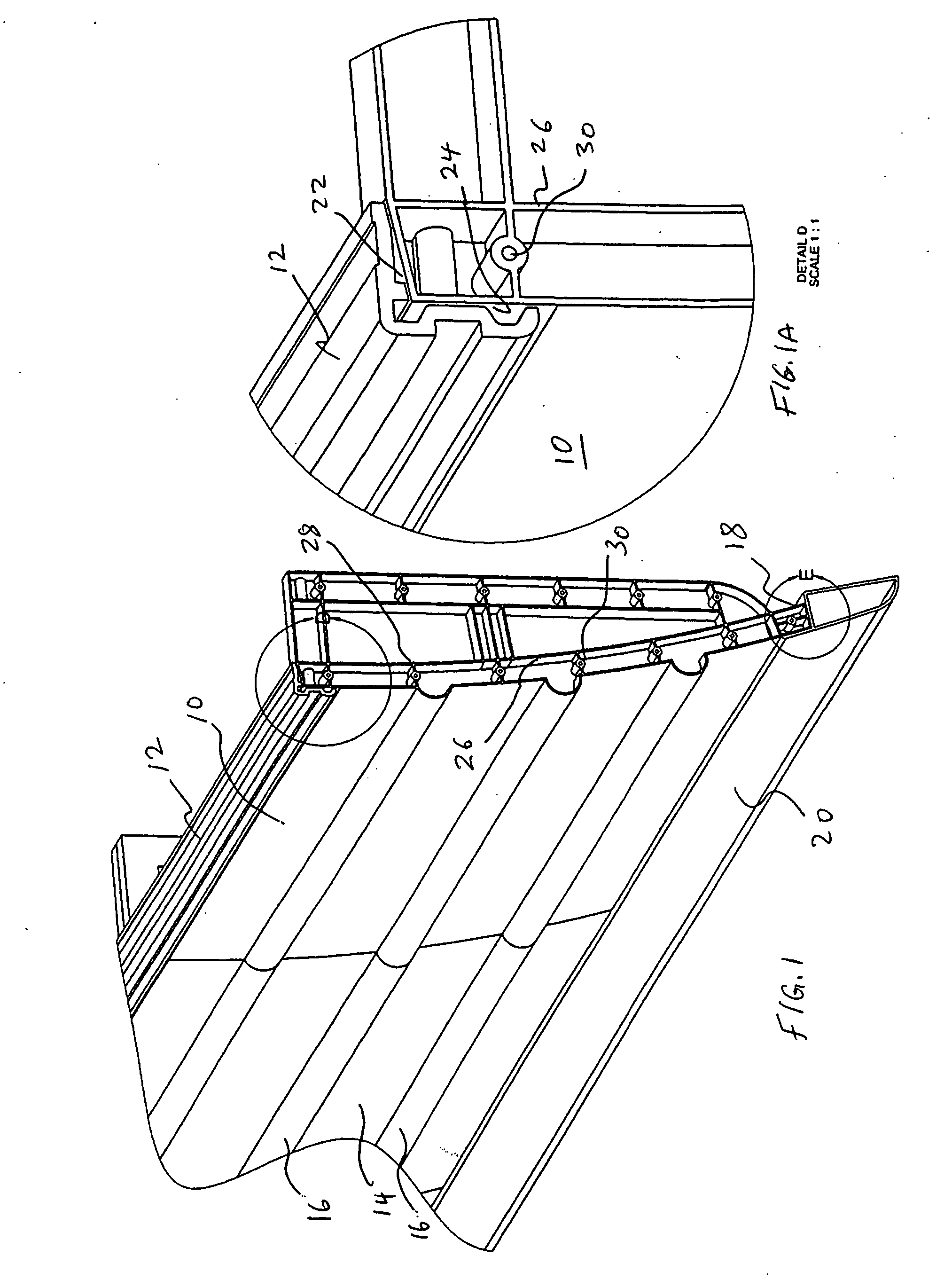
Each of the above patented devices, though providing improvements in the art, have failed to adequately provide an aerodynamic side panel structure which presented a durable and easy to use fixed structure for accomplishing
airflow improvement around a tractor-
trailer truck.
Some disclosed structures used very rigid side panels, which were difficult to maintain in position, and were awkward to
handle.
Some structures required cumbersome tensioning means to maintain the skirt or deflector in position.

