Enclosure For An Unmanned Aerial System

an unmanned aerial system and enclosure technology, applied in the field of enclosures, can solve the problems of difficult to carry a uas, no longer effective mission, slow military ground vehicles, etc., and achieve the effect of facilitating air passag

Active Publication Date: 2019-10-10
UNITED STATES OF AMERICA THE AS REPRESENTED BY THE SEC OF THE ARMY
View PDF0 Cites 26 Cited by
  • Summary
  • Abstract
  • Description
  • Claims
  • Application Information

AI Technical Summary

Benefits of technology

[0019]An enclosure for a UAS according still another exemplary embodiment includes a housing defining an interior volume, an actuator mounted within the interior volume, a platform coupled to the actuator and configured to move generally vertically within the interior volume under control of the actuator, first and second non-metallic lids movable between open and closed positions under control of the actuator, a plurality of airflow management vents formed in the housing, a plurality of guides coupled to the platform, a plurality of retainers, and a power connector coupled to the platform and configured to engage a complementary power connector on the UAS. Furthermore, each of the first and the second lids is pivotably coupled between the housing and the platform via a multi-segment linkage. Each of the multi-segment linkages can include three segments and a mechanical adjustment feature as described above. Furthermore, the platform defines an opening therethrough as well as a generally uniform gap around a perimeter of the platform between the platform and the housing, whereby the opening and the gap facilitate the movement of air passed the platform. Additionally, the guides are configured to slidably engage respective landing supports of the UAS and to guide each of the landing supports along a plurality of directions into a predetermined position on the platform between an inside apex of the guide and the opening. The plurality of retainers is mounted on inside surfaces of each of the first and second lids, whereby the retainers are positioned to urge the UAS toward the platform when the lid is in the closed position. Driving the actuator in a first direction raises the platform and opens the first and the second lids, whereas driving the actuator in a second direction opposite the first direction lowers the platform and closes the first and the second lids.

Problems solved by technology

Because military ground vehicles are relatively slow, especially when operating off-road, enemies will attempt to spring traps and / or attack them by surprise.
Furthermore, while many ground vehicles have armor plating to protect the occupants inside, only so much armor can be added to a vehicle before the vehicle becomes so heavy that it can no longer perform its mission effectively.
Unfortunately, it is difficult to carry a UAS on a military ground vehicle, because such vehicles face harsh operating conditions such as high ambient temperatures, direct extended sun, sand, high winds, increased vibration, etc. which can damage and / or degrade vehicle systems.
Such structures have been proposed in the prior art, but unfortunately, are not sufficiently rugged for military use.
Additionally, such prior art structures suffer disadvantages such as having large footprints and / or form factors, complex operating mechanisms, etc.

Method used


Image

  • Enclosure For An Unmanned Aerial System
  • Enclosure For An Unmanned Aerial System
  • Enclosure For An Unmanned Aerial System

Examples


Embodiment Construction

[0038]As required, detailed embodiments of the present invention are disclosed herein; however, it is to be understood that these embodiments are merely exemplary of the invention that may be embodied in various and alternative forms. The figures are not necessarily to scale; some features may be exaggerated or minimized to show details of particular components. Therefore, specific structural and functional details disclosed herein are not to be interpreted as limiting, but merely as a representative basis for teaching one skilled in the art to variously employ the present invention. In other instances, particulars of well-known components and manufacturing practices (e.g., actuator control, metal forming, etc.) have been omitted so as to not unnecessarily obscure the present invention.

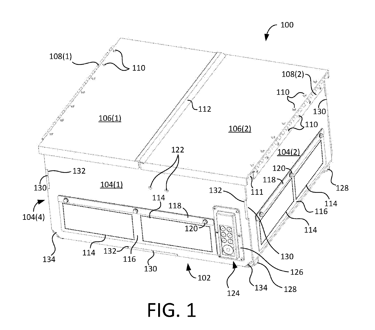
[0039]FIG. 1 is a front perspective view showing an enclosure 100 for housing an unmanned aerial system (UAS), such as a multi-rotor unmanned aerial vehicle (UAV), therein. Enclosure 100 includes a ba...


PUM


Abstract

An enclosure for a UAS includes a housing having a base and a plurality of sidewalls coupled to the base, a motive apparatus coupled to the housing, a platform coupled to the motive apparatus, and a plurality of lids pivotably coupled to the sidewalls and the platform. The platform and the plurality of lids move collectively under control of the motive apparatus (e.g., a linear actuator). Driving the motive apparatus in a first direction causes the platform to raise from a stowed position toward a deployed position and causes each of the plurality of lids to pivot from a closed position toward an open position. Conversely, driving the motive apparatus in a second direction opposite the first direction causes the platform to lower from the deployed position toward the stowed position and causes each of the plurality of lids to pivot from the open position toward the closed position.

Description

CROSS-REFERECE TO RELATED APPLICATIONS[0001]This application claims the benefit of co-pending U.S. Provisional Patent Application Ser. No. 62 / 655,679, filed on Apr. 10, 2018, by at least one common inventor, which is incorporated by reference herein in its entirety.GOVERNMENT INTEREST[0002]The inventions described herein may be made, used, or licensed by or for the U.S. Government for U.S. Government purposes without payment of royalties to me / us.BACKGROUND OF THE INVENTIONField of the Invention[0003]The present invention relates generally to enclosures and, more particularly, to an enclosure for an unmanned aerial system (UAS). Even more particularly, the invention relates to an enclosure configured to carry a UAS on a ground vehicle.[0004]Description of the Background Art[0005]Unmanned aerial systems (UAS) include autonomous, semi-autonomous, and / or remote controlled devices configured for flight. UAS are available in a variety of form factors, including camera drones, aerial vehi...

Claims


Application Information

Patent Timeline
Patent Type & Authority Applications(United States)
IPC IPC(8): B64C39/02
CPCB64C2201/042B64C39/024B64C2201/141B64C2201/201B64F1/222B64U80/70B64U50/19B64U2201/10
Inventor COOPER, NEIL E.PATERNOSTER, ERIC S.SCHRADER, JASON A.BRONSTETTER, GARY L.
Owner UNITED STATES OF AMERICA THE AS REPRESENTED BY THE SEC OF THE ARMY
Why Eureka
Try Eureka