Evaporator

Inactive Publication Date: 2009-11-19
KEIHIN THERMAL TECH CORP
View PDF0 Cites 26 Cited by
  • Summary
  • Abstract
  • Description
  • Claims
  • Application Information

AI Technical Summary

Benefits of technology

[0031]With the evaporator of par. 9), while an increase of air flow resistance is suppressed, heat exchange performance is enhanced, thereby establishing good balance between air flow resistance and heat exchange performance.

Problems solved by technology

However, in the case where the quantity of condensed water is large, a large quantity of condensed water stagnates at the joint portions, and is not drained sufficiently from the front-end side, which raises a problem in that when the flow rate of air abruptly changes, the condensed water scatters, or the condensed water closes the clearances between louvers by means of surface tension to thereby lower cooling performance.
Moreover, the condensed wat

Method used


Image

  • Evaporator
  • Evaporator
  • Evaporator

Examples


Example

Embodiment 1

[0047]The present embodiment is illustrated in FIGS. 1 to 9.

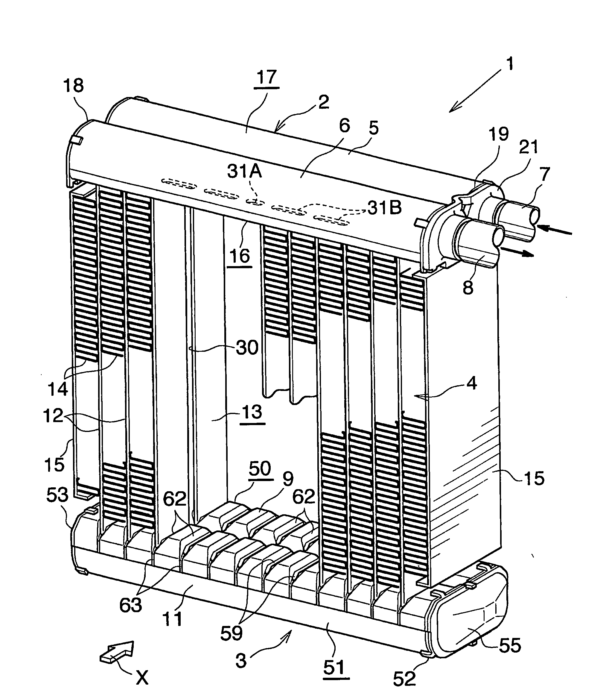
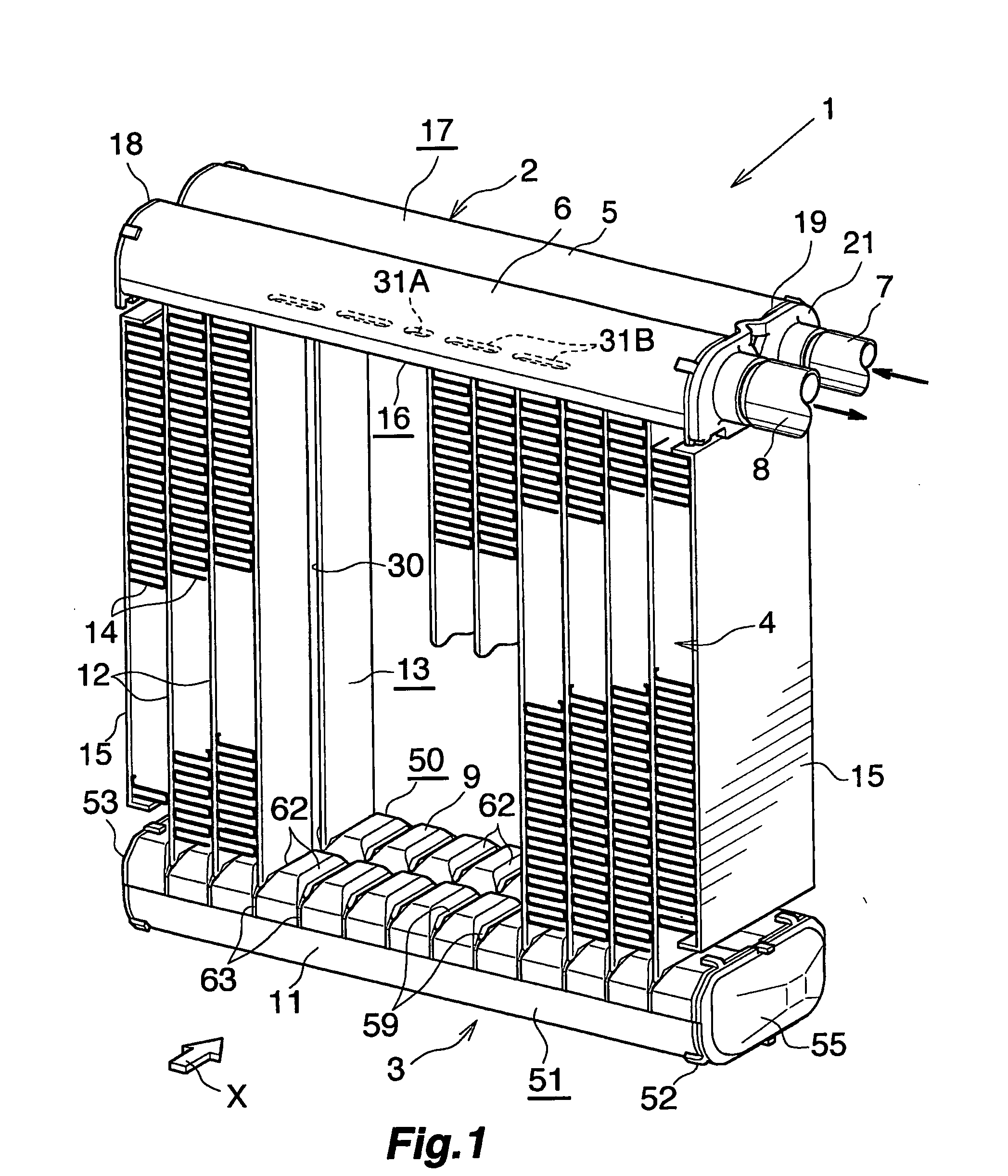
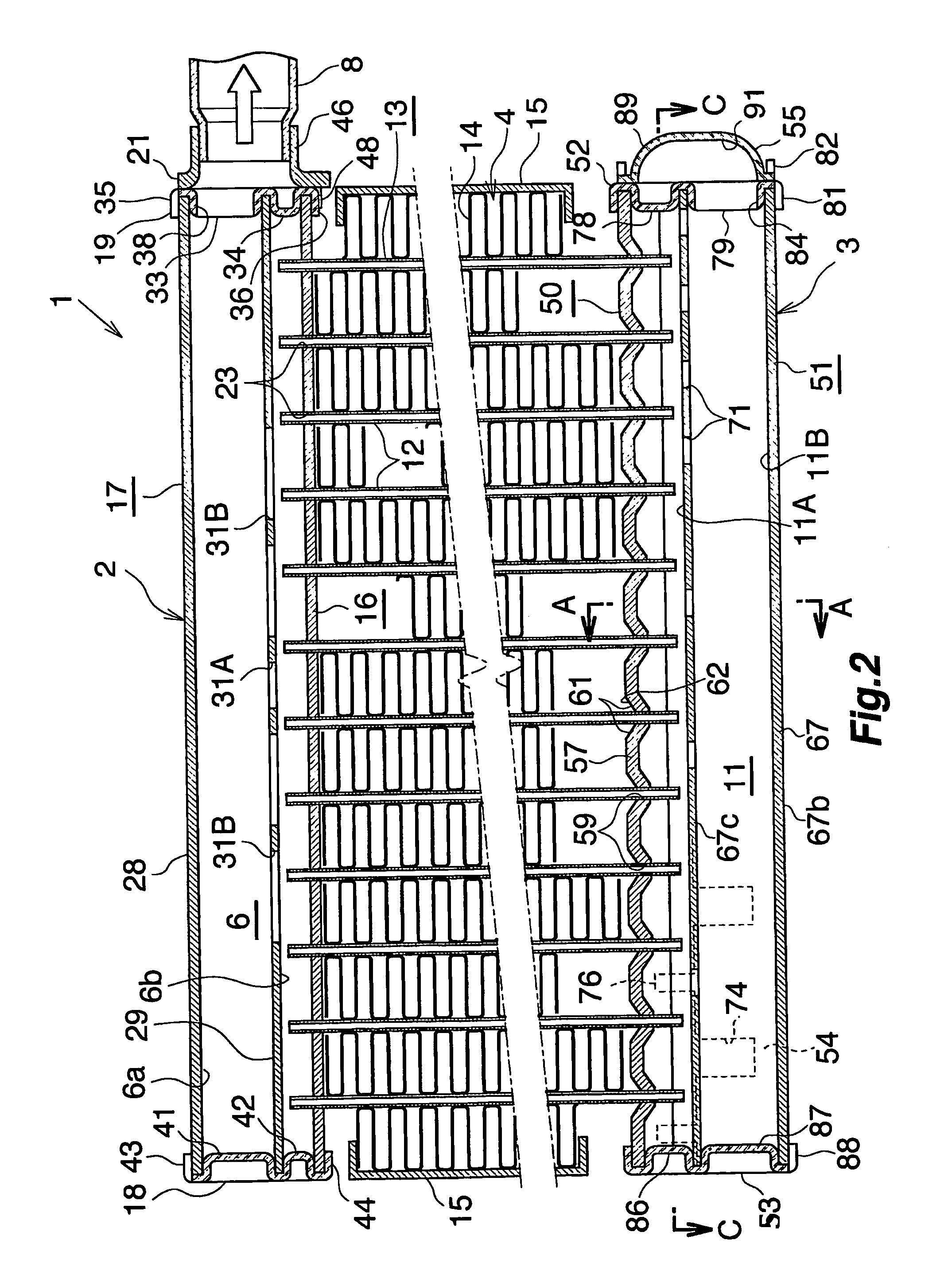
[0048]FIGS. 1 and 2 show the overall configuration of an evaporator, and FIGS. 3 to 8 show the configuration of essential portions of the evaporator. FIG. 9 shows how a refrigerant flows in the evaporator.

[0049]In FIGS. 1 and 2, the evaporator (1), which is used in a car air conditioner using a chlorofluorocarbon-based refrigerant, includes a refrigerant inlet / outlet tank (2) made of aluminum and a refrigerant turn tank (3) made of aluminum, the tanks (2) and (3) being vertically spaced apart from each other, and further includes a heat exchange core section (4) provided between the tanks (2) and (3).

[0050]The refrigerant inlet / outlet tank (2) includes a refrigerant inlet header section (5) located on a side toward the front (downstream side with respect to the air flow direction) and a refrigerant outlet header section (6) located on a side toward the rear (upstream side with respect to the air flow direction)....

Example

Embodiment 2

[0093]The present embodiment is illustrated in FIGS. 10 to 13.

[0094]In the present embodiment, the evaporator (100) is configured such that a plurality of refrigerant flow members (101) each having a vertically elongated rectangular shape are arranged in a laminated condition in the left-right direction and joined together while their widths extend in the front-rear direction (air flow direction).

[0095]Each of the refrigerant flow members (101) includes two vertically extending rectangular aluminum plates (102) whose peripheral edge portions are brazed together. Each of the aluminum plates (102) is formed from an aluminum brazing, sheet having a brazing material layer on each of opposite sides thereof. Two (front and rear) vertically extending, bulging refrigerant flow tube portions (103) and (104), and bulging header formation portions (105) and (106) are provided between the two aluminum plates (102), which partially constitute the refrigerant flow member (101). The bu...


PUM

PropertyMeasurementUnit
Thicknessaaaaaaaaaa
Thicknessaaaaaaaaaa
Radiusaaaaaaaaaa

Abstract

An evaporator includes plural refrigerant flow members and corrugate fins disposed in corresponding air-passing clearances between the adjacent refrigerant flow members. Each refrigerant flow member includes plural flat tubes arranged in the front-rear direction. Each corrugate fin extends across all the flat tubes. A vertically extending drain portion is formed between the flat tubes adjacent each other in the front-rear direction. At each connection portion of the corrugate fin, a louver group including plural louvers inclining downward toward the front is provided to correspond to a front portion of each flat tube. At least the front-end louver of the louver group provided to correspond to the front portion of each flat tube except for the flat tube at the front end is located in the drain portion. This evaporator exhibits excellent drainage of condensed water and enables high work efficiency in manufacture thereof.

Description

CROSS REFERENCE TO RELATED APPLICATIONS[0001]This application is an application filed under 35 U.S.C. § 111(a) claiming the benefit pursuant to 35 U.S.C. § 119(e)(1) of the filing date of Provisional Application No. 60 / 637,745 filed Dec. 22, 2004 pursuant to 35 U.S.C. § 111(b).TECHNICAL FIELD[0002]The present invention relates to an evaporator to be built in, for example, a car air conditioner.[0003]Herein and in the appended claims, the upper and lower sides of FIGS. 1, 2, and 10 will be referred to as “upper” and “lower,” respectively. The downstream side of an air flow (a side represented by arrow X in FIGS. 1 and 10, and a right-hand side in FIG. 4) is referred to as the “front,” and the opposite side as the “rear.” The left-hand and right-hand sides of FIGS. 2 and 10 will be referred to as “left” and “right,” respectively.BACKGROUND ART[0004]A conventionally used evaporator for use in a car air conditioner includes a plurality of refrigerant flow members arranged in parallel, a...

Claims


Application Information

Patent Timeline
IPC IPC(8): B60H1/32F28F1/10F28F9/02F25B1/00
CPCF25B39/02F28D1/0333F28D1/05391F28D2021/0085F28F1/128F28F9/0214Y10T29/4935F28F9/0246F28F9/0253F28F9/0278F28F17/005F28F2220/00F28F9/0224
Inventor HIGASHIYAMA, NAOHISA
Owner KEIHIN THERMAL TECH CORP
Why Eureka
Try Eureka