
Direct injection internal combustion engine

a technology of internal combustion engine and injection time, which is applied in the direction of electric ignition installation, machines/engines, mechanical equipment, etc., can solve the problems of limiting injection time and mixture formation, and achieve the effect of low fuel consumption and low exhaust emissions

Inactive Publication Date: 2002-04-30
AUDI AG
View PDF4 Cites 28 Cited by
  • Summary
  • Abstract
  • Description
  • Claims
  • Application Information

AI Technical Summary

Benefits of technology

In this context it is the object of this invention to design an improved direct injection internal combustion engine and a process of mixture preparation characterized in homogeneous lean fuel operation and in stratified lean fuel operation by low fuel consumption and by low exhaust emissions.
In accordance with an advantageous development of the invention, the intake valves should be spaced the maximum distance from each other to sustain the tumble flow of fresh air. This feature also favors mounting of the injection valve between the intake valves.
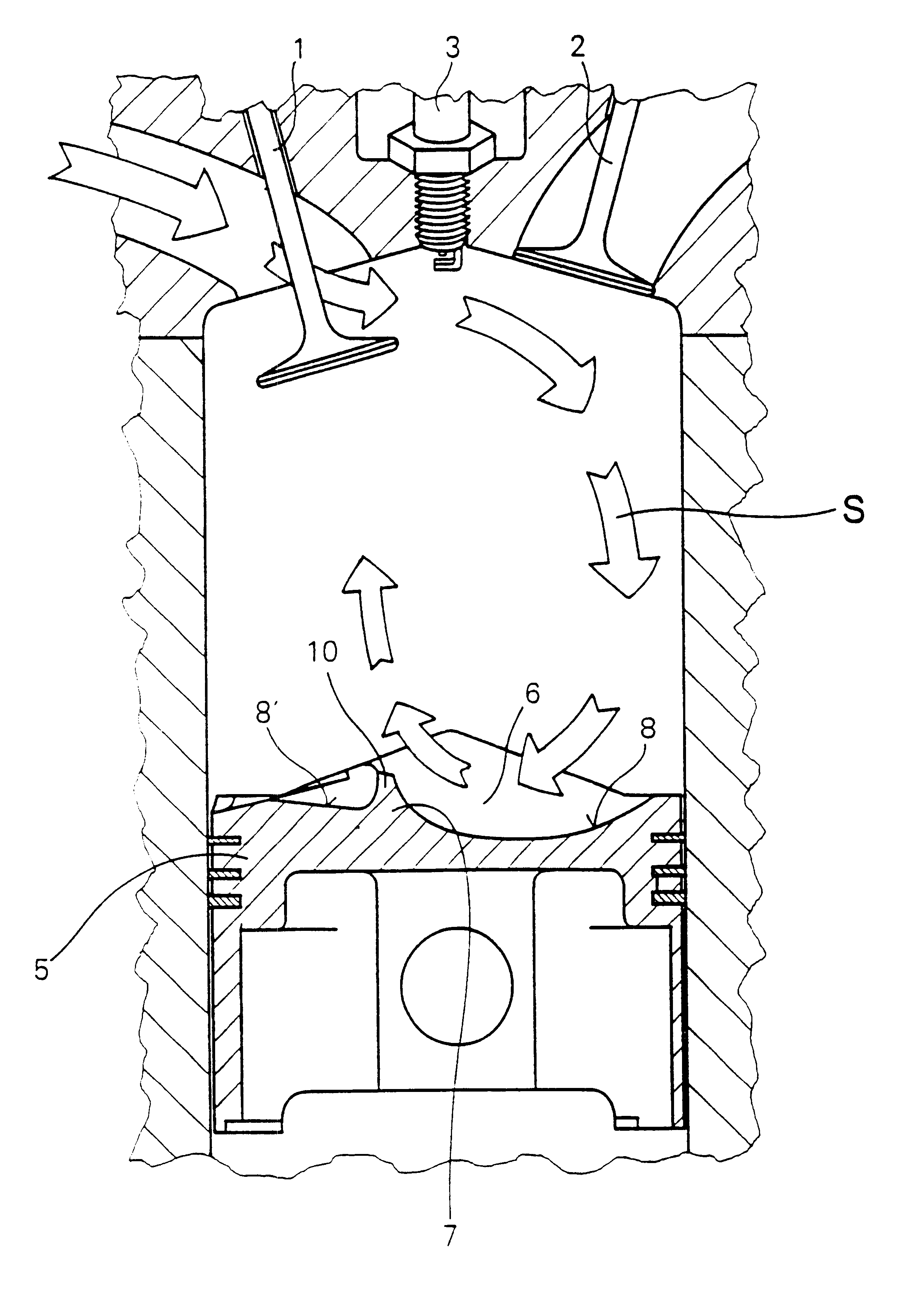
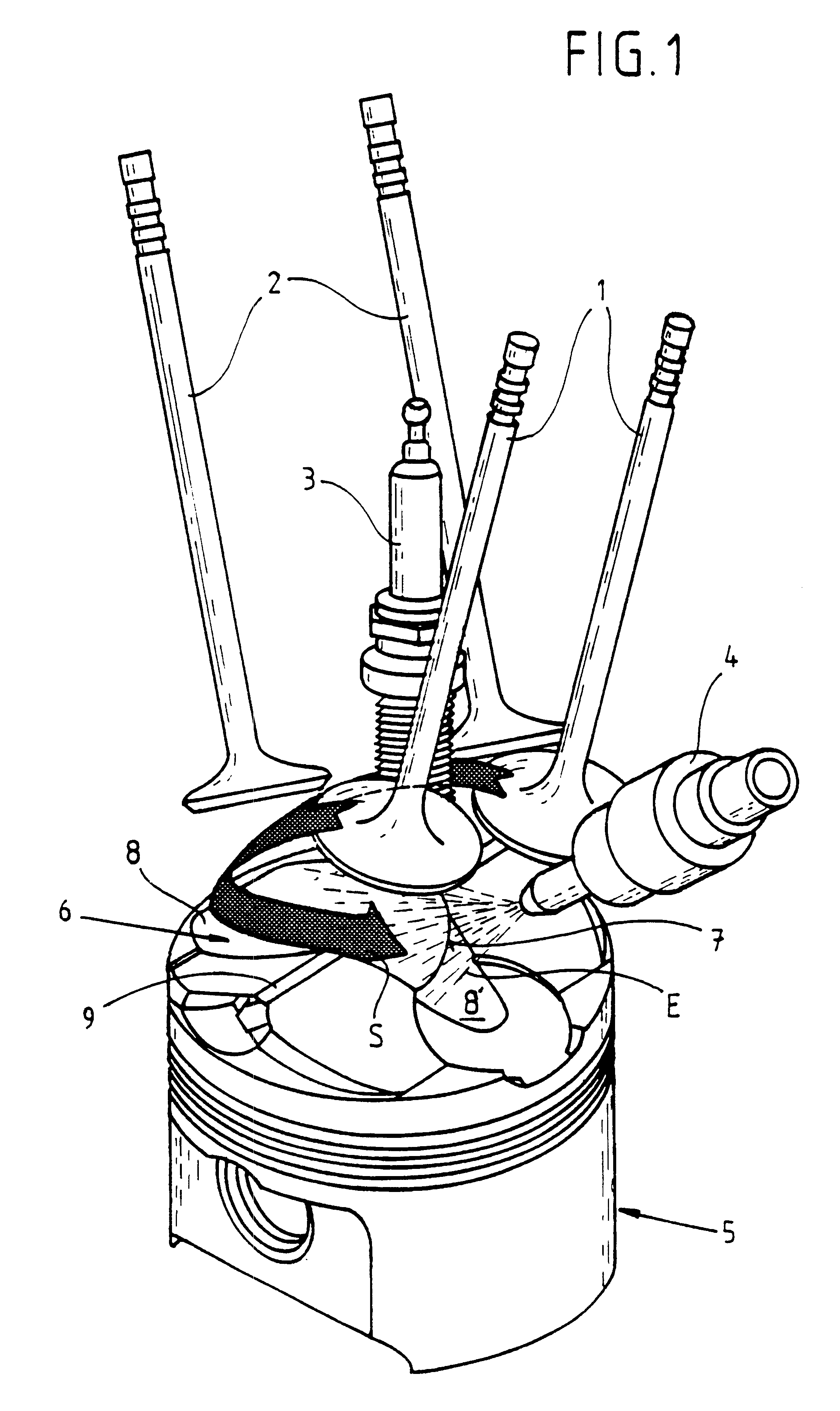
And for stratified lean fuel operation the injection valve injects fuel into the cylinder during the compression stroke with the crankshaft at an angle of approximately 120 to 30 degrees, before the piston reaches upper dead center. Hence the fuel is injected for the most part in advance of the fresh air tumble flow, is stabilized by the fresh air flow within the area of the combustion chamber trough as an ignitable fuel charge spray, and lastly is transported to the spark plug. In the process the oblong combustion chamber trough with step extending crosswise serves to guide or concentrate the fresh air tumble flow and to stabilize the ignitable mixture spray formed from the flow. This process can be completed despite the relatively late injection time.
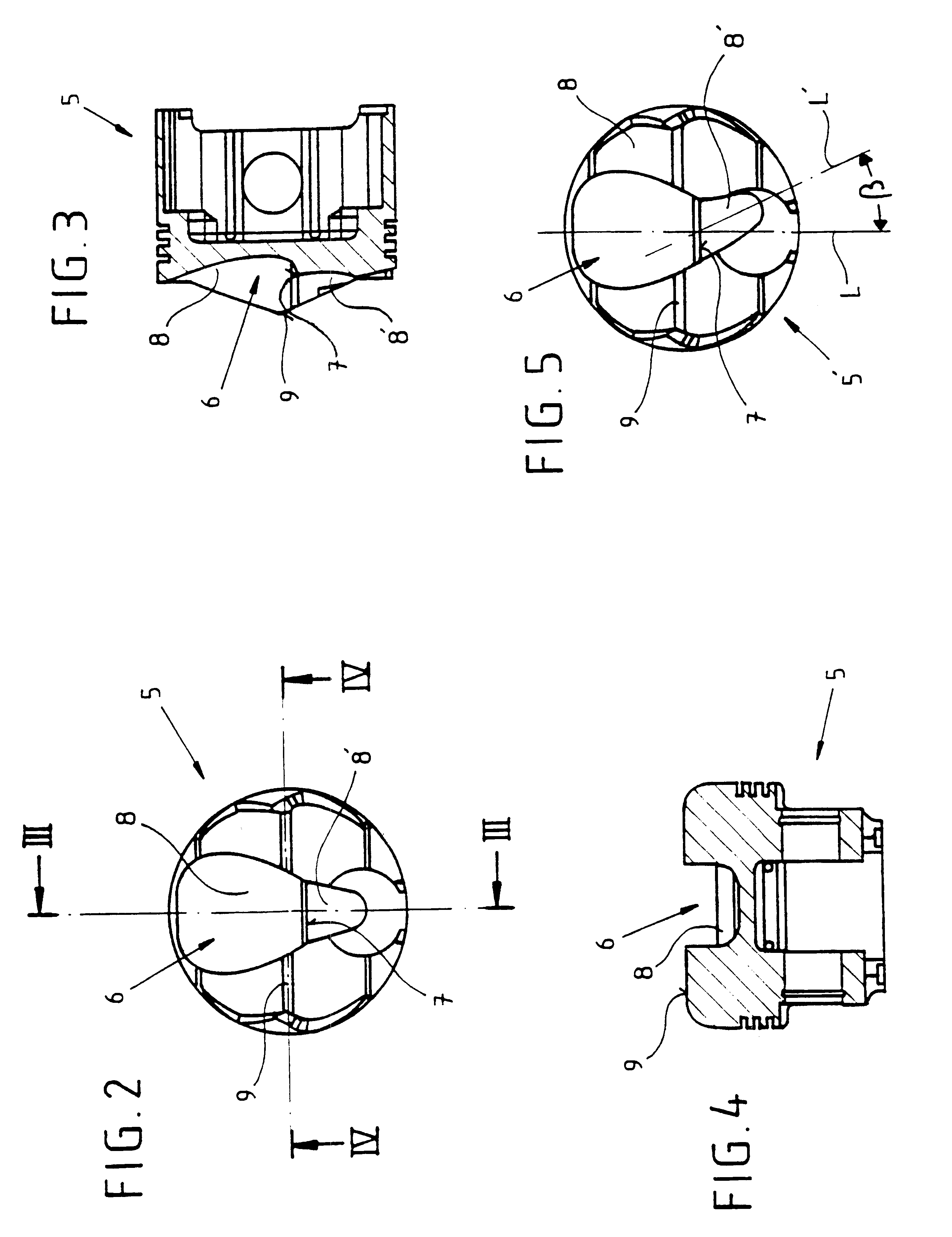
By preference the step which divides the combustion chamber trough into a first area remote from the injection valve and a second area near the injection valve takes place more or less below the spark plug. As a result the first area allows efficient guidance of the fresh air tumble flow and the centrally positioned second step favorable deflection of the fresh air flow, while the second area effects adequate stabilization of the fuel charge spray near the spark plug. By special preference the first area of the combustion chamber trough is designed to be deeper than the second area, since this feature facilitates deflection of the fresh air tumble flow by the step representing transition from the deep area to the shallow area. However, the first area of the combustion chamber trough may, of course, also be designed to be shallower than the second area. Lastly, each of the two areas of the combustion chamber trough may also be designed to incline at a slight angle toward the edge of the piston. This results in particularly gentle flow of fresh air into the first area and of fuel into the second area of the combustion chamber trough.
In accordance with a development of the invention the oblong combustion chamber trough widens in the direction of the injection stream. As a result, the fresh air tumble flow is concentrated or focused in the combustion chamber trough, and this facilitates thorough mixing of fresh air and fuel. Similarly, the first area of the combustion chamber trough may be wide, more or less parabolic, in shape, while the second area may be in the form of a narrow corridor. These shapes are optimally adapted to the fresh air flowing in through at least two intake valves and correspondingly to the fuel injected through the injection valve.
Additional optimization of mixture preparation in this direct injection internal combustion engine is achieved by forming on the step extending more or less crosswise in the oblong combustion chamber trough a fin which extends over the entire length of the step. The fresh air tumble flow is especially favorably guided and maintained for a prolonged period during compression and injection, and the fuel stream, which is injected more or less in a straight line, is deflected upward by the fin. These two factors result in very decidedly improved mixture preparation, so that a direct injection internal combustion engine characterized by markedly low fuel consumption and especially low exhaust gas emissions is created.

Problems solved by technology

However, the time required for preparation of a homogeneous lean mixture limits the injection time.
On the other hand, in order to obtain a local area with a combustible fuel / air mixture, it is necessary to be only very late in introducing the fuel, something which creates problems in mixture formation.

Method used


Image

  • Direct injection internal combustion engine
  • Direct injection internal combustion engine
  • Direct injection internal combustion engine

Examples


Embodiment Construction

The internal combustion engine claimed for the invention as shown in FIG. 1 is provided with two intake valves 1 per cylinder mounted side by side. These two intake valves 1 are positioned on a side half of a cylinder not shown and two exhaust valves 2 also mounted side by side are positioned on the other side half of the cylinder. In addition, the internal combustion engine has a spark plug 3 mounted concentrically with the axis of the cylinder. One injection valve 4 is also provided per cylinder; this valve 4 is mounted between the two intake valves 1 and the section of the cylinder wall adjoining the two intake valves. The piston 5 mounted in the cylinder of the internal combustion engine has an oblong combustion chamber trough 6 with step 7 extending crosswise.

The fresh air flowing into the cylinder through the two intake valves 1 forms a tumble flow S inside the combustion chamber. Formation of the tumble flow S is enhanced if the two intake valves 1 are spaced the maximum dist...


PUM


Abstract

The invention relates to an internal combustion engine with direct fuel injection comprising at least two adjacent inlet valves (1) per cylinder, a number of outlet valves (2), an essentially coaxial spark plug (3), an injection valve (4) and a piston (5,5'). The aim of the inventive engine is to provide an improved mixture preparation which is characterized by low fuel consumption and low exhaust emissions. To this end, the injection valve (4) is arranged between two of the adjacent inlet valves (1) and the section of the cylinder wall adjacent to said inlet valves (1). in addition, the piston (5,5') has a longitudinally extended combustion chamber cavity (6), whereby the combustion chamber cavity (6) essentially extends along the front surface of the piston (5,5') in the direction of the vertical projection of an injection stream (E) exiting from the injection valve (4). Said cavity also comprises a step (7) which essentially runs in a transversal direction.

Description

This invention relates to a direct injection internal combustion engine which has at least two intake valves per cylinder mounted side by side, a plurality of exhaust valves, a more or less coaxial spark plug, an injection valve, and a piston. The invention also relates to a process for mixture preparation in a direct injection internal combustion engine.BACKGROUND OF INVENTIONAn internal combustion engine and a process such as this are known, for example, from The Ford PROCO Engine Update," Scussel A. J. et al., SAE 780699. In this instance fuel is injected directly into a cylinder of an internal combustion engine by means of a high-pressure injection nozzle. However, the time required for preparation of a homogeneous lean mixture limits the injection time. On the other hand, in order to obtain a local area with a combustible fuel / air mixture, it is necessary to be only very late in introducing the fuel, something which creates problems in mixture formation.SUMMARY OF INVENTIONIn t...

Claims


Application Information

Patent Timeline
IPC IPC(8): F02B31/00F02B23/10F02B31/08F02F1/42F02B75/12F02F1/24F02B75/00F02F3/26F02P13/00
CPCF02B23/104F02B31/085F02F1/4214F02B2023/106F02B2075/125Y02T10/123F02F2001/241F02F2001/245Y02T10/125Y02T10/146F02F3/26Y02T10/12
Inventor OTTOWITZ, ALFREDRIEGER, THOMASWERMUTH, DIETMARSCHLADT, THOMASSERIFSOY, MURATWURMS, RAINERFALTERMEIER, GEORGBUDACK, RALF
Owner AUDI AG
Learn More