Sawdust collection hood for table saw

Inactive Publication Date: 2005-05-12
JORGENSEN MATTHEW R
View PDF7 Cites 26 Cited by
  • Summary
  • Abstract
  • Description
  • Claims
  • Application Information

AI Technical Summary

Benefits of technology

[0010] Although rotation of the saw blade is sufficient to create the above-described air stream, the air stream flow rate can be increased by attaching a vacuum source to the hood. Therefore, in a preferred embodiment, the hood further includes a rear discharge wall mounted between an upper surface of a central portion of the lower cowl and the rear edge of the upper cowl.

Problems solved by technology

Such heretofore known protective hoods, however, failed to adequately rem

Method used


Image

  • Sawdust collection hood for table saw
  • Sawdust collection hood for table saw
  • Sawdust collection hood for table saw

Examples


first embodiment

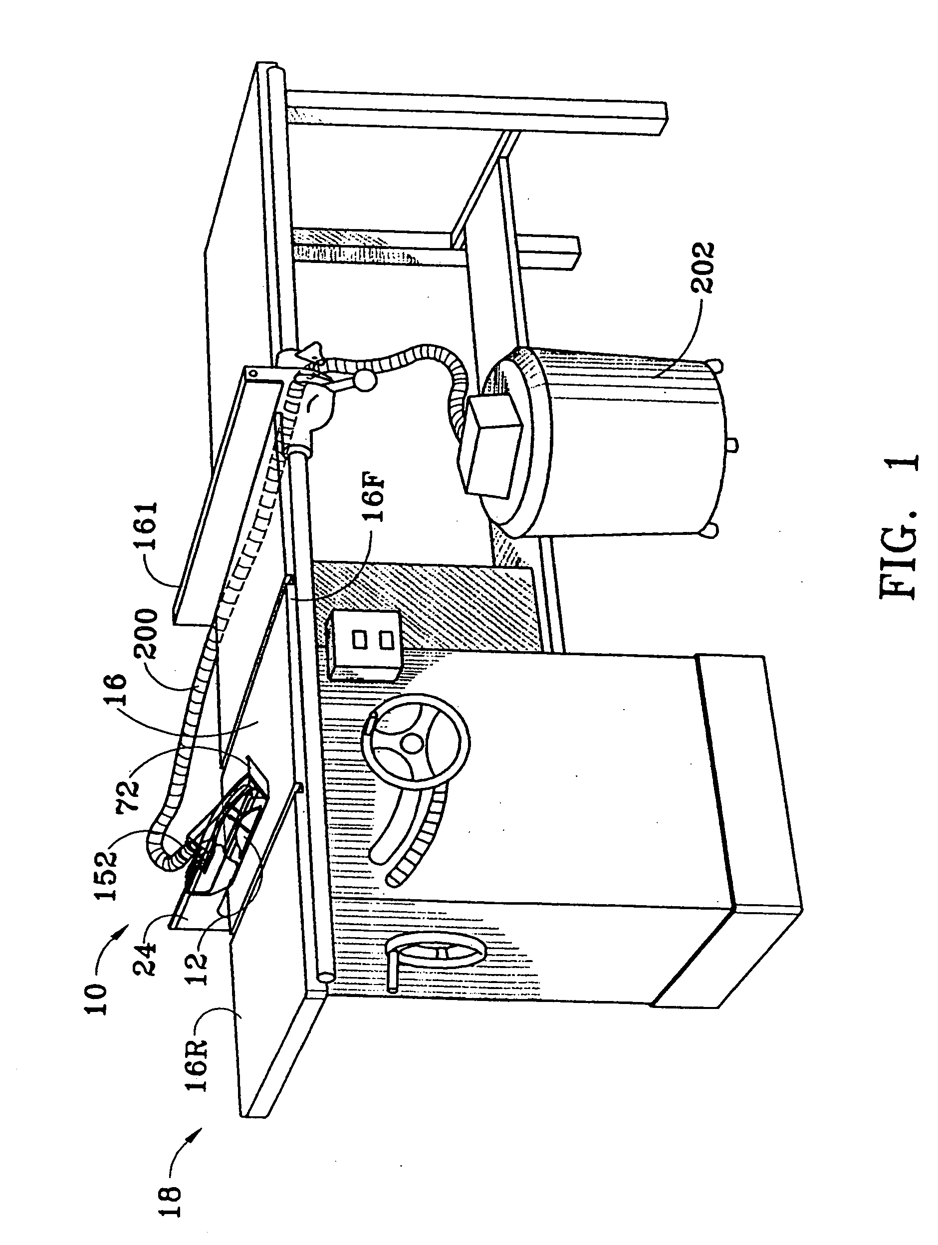
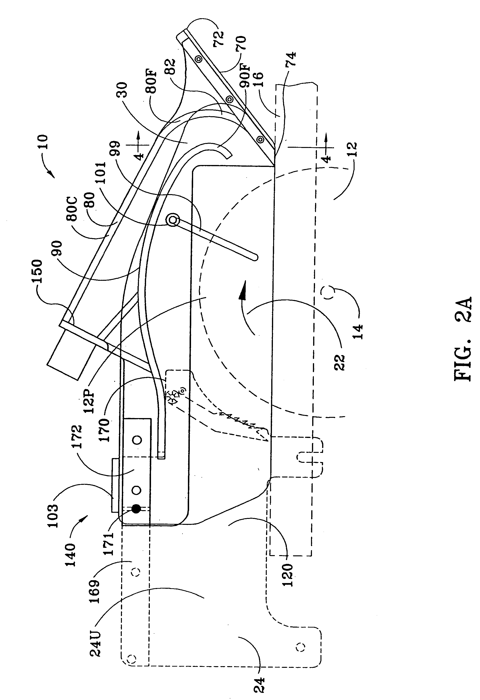
[0044] Referring now to FIGS. 1, 2A, 2B and 2C, a movable, protective hood 10, denoted generally by the numeral 10, is shown in a working position directly over and straddling a rotary saw blade 12 mounted on a drive shaft 14 located below a flat, horizontal work table 16 of a rotary table saw 18. An exposed, upper, peripheral portion 12P of the saw blade 12 protrudes through a slot (not shown) in the work table 16 and, as denoted by arrow 22, rotates forwardly toward a front edge 16F of the work table 16. The table saw 18 is equipped with a splitter 24, shown in dashed outline, mounted to a rear portion 16R of the work table 16. The splitter 24 is aligned with, and disposed directly behind, the saw blade 12. In this first embodiment of the hood, the hood 10 is pivotally mounted to the splitter 24, as described below.

[0045] The hood 10 comprises a pair of spaced-apart vertical side panels 30 of identical size and shape, each side panel being longitudinally elongated from front to re...

third embodiment

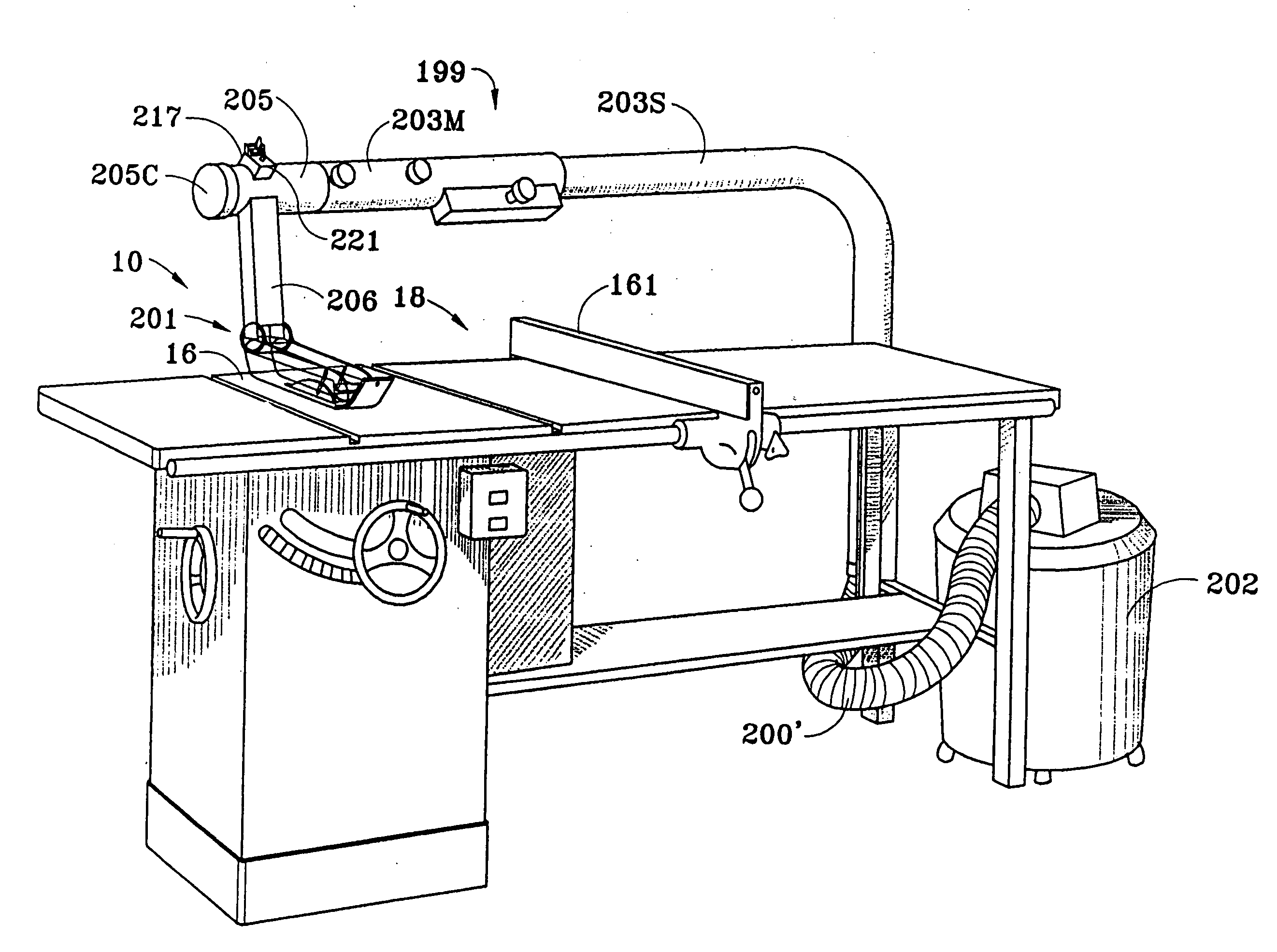
[0054] In the hood 10, depicted in FIGS. 9-15, the hood 10 is pivotally attached by a collar joint 201 to an overhead vacuum conduit assembly 199. The conduit assembly 199 includes a vacuum source 202 connected to an electric power source (not shown), a laterally disposed, elongated, cylindrical, hollow boom 203, and a hollow head stock 205 attached to one end of the boom 203. A movable vacuum hose 200 within the boom 203 has a discharge end that terminates in a ring seal 197 and an opposite, intake end that is normally stored within the head stock 205. The ring seal 197 has an outer diameter slightly less than the inner diameter of the boom 203 in order to maintain a vacuum throughout the interior of the boom 203. The ring seal 197 is slidable within the boom 203, its extent of travel being limited by a lock plate 153P within the head stock 205. A vacuum source 202 is attached to the discharge end of the boom 203 by a stationary hose 200′ that inserts into an annular seal 39 at sai...


PUM


Abstract

A sawdust collection hood for a table saw. The hood has an identical pair of vertical, spaced-apart side panels, an upper cowl mounted between the side panels, a canted nose panel mounted between front portions of the side panels, and a lower cowl that extends rearwardly between the side panels below the upper cowl from a forward edge of the lower cowl disposed over a trailing edge of the nose panel. A pair of side skirts suspended from each of the side panels, extend rearwardly from the nose panel, and are movable between a raised and a lowered position. When placed upon the saw work table, straddling the saw blade, and with side skirts lowered, a work piece moved rearward against the canted nose panel causes the hood to rise. As the work piece progresses rearwardly past the saw blade, the side skirts remain lowered, resting on the work piece, until the work piece just clears the nose panel, whereupon the hood drops down to the work table, raising the skirts relative to the nose panel and closing a gap that would otherwise permit sawdust to escape below the front of the hood. The hood may be pivotally attached to a table saw splitter or, alternatively, may be pivotally attached by a collar joint to an overhead vacuum conduit assembly.

Description

CROSS-REFERENCE TO RELATED APPLICATION [0001] This application is a continuation application of U.S. patent application Ser. No. 09 / 253,110 filed Feb. 19, 1999, and is incorporated by reference in its entirety.BACKGROUND OF THE INVENTION [0002] 1. Field of the Invention [0003] This invention relates to a movable, protective, sawdust collection hood for use with a table saw equipped with a rotary saw blade and, more particularly, to such a hood that provides a directed air stream for removal of sawdust generated by a saw blade rotating on a shaft located below a work table. [0004] 2. Background Art [0005] Protective hoods have become widely used to remove sawdust generated by the cutting of a work piece on a rotary table saw, and to conduct the dust toward a sawdust collection receptacle. The hoods have additionally served to protect the user thereof from injury due to inadvertent contact with a rotating saw blade. Such hoods have generally taken the form of a longitudinally elongate...

Claims


Application Information

Patent Timeline
IPC IPC(8): B23Q11/00B27G19/02
CPCB23D59/006B27G19/02B23Q11/0046Y10T83/207Y10T83/773Y10T83/7734
Inventor JORGENSEN, MATTHEW R.
Owner JORGENSEN MATTHEW R
Why Eureka
Try Eureka