
Polygonal ridge flow classification

a polygonal ridge and classification technology, applied in the field of print image analysis, can solve the problems of early identification of unsuitable print images, and achieve the effects of easy identification, fast classification, and meaningful visual feedback

Inactive Publication Date: 2005-02-17
AUTHORIZER TECH INC
View PDF4 Cites 29 Cited by
  • Summary
  • Abstract
  • Description
  • Claims
  • Application Information

AI Technical Summary

Benefits of technology

[0017] An advantage of embodiments are conventional flood-fill algorithms can be used in the present invention to classify a print image quickly. Further, these flood-fill algorithms are used to generate display outputs of fingerprint images that provide fast, meaningful visual feedback to a user. Among other things, these display outputs allow a user to easily identify ridge flow patterns and regions with singularity point(s) in a captured print image.

Problems solved by technology

In this way, unsuitable print images are identified early.

Method used


Image

  • Polygonal ridge flow classification
  • Polygonal ridge flow classification
  • Polygonal ridge flow classification

Examples


Embodiment Construction

)

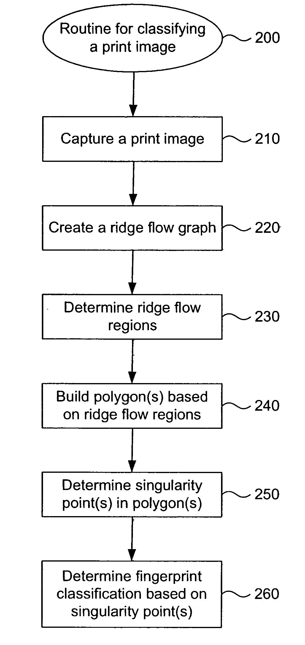
[0030] Polygonal Ridge Flow Classification

[0031] Overview

[0032] An embodiment of the present invention provides a process in which a ridge flow analysis of a fingerprint image can be used to determine a fingerprint classification. Areas of like valued ridge flow are collected as regions and said regions are then joined together when edges of the regions exist. These vertices are then reduced to for polygons including, but not limited to, minimal circular-like or regular polygons. Each polygon is characterized by the number of vertices that create them. Polygons that have a predetermined number of vertices (i.e., eight vertices for the case of 8 ridge flow directions) and contain one value from each of the possible ridge flow values from the ridge flow table are deemed to be a singularity. In one example, these singularities are then further identified based on a clockwise or counter-clockwise direction. Clockwise singularities are identified as cores and counter-clockwise singula...


PUM


Abstract

A process in which a ridge flow analysis of a fingerprint image can be used to determine a fingerprint classification. Areas of like valued ridge flow are collected as regions and said regions are then joined together when edges of the regions exist. These vertices are then reduced to form polygons. Polygons that have a predetermined number of vertices (i.e., 8) and contain values from across a range of the possible ridge flow values (i.e., one of each possible ridge flow value) from the ridge flow table are primary polygons associated with singularity points. These singularity points are further identified as cores or deltas allowing the print image to be globally classified as loop, arch or whorl. Further techniques including, but not limited to, ridge counting can be used to classify the fingerprint as a left or right loop, plain or tented arch, or whorl.

Description

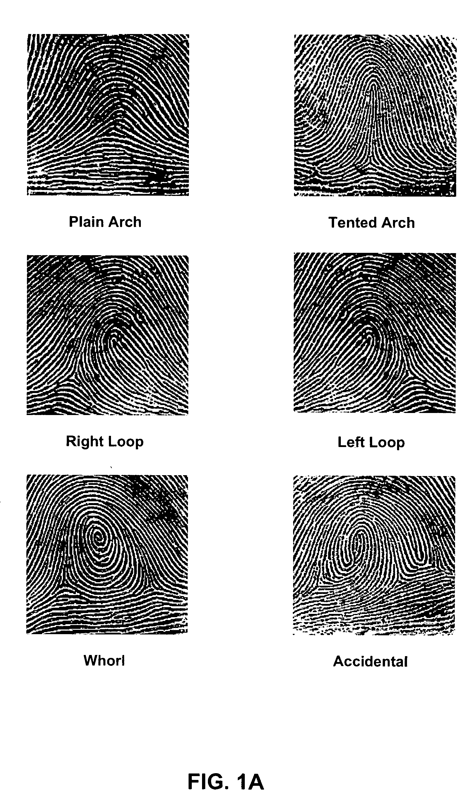
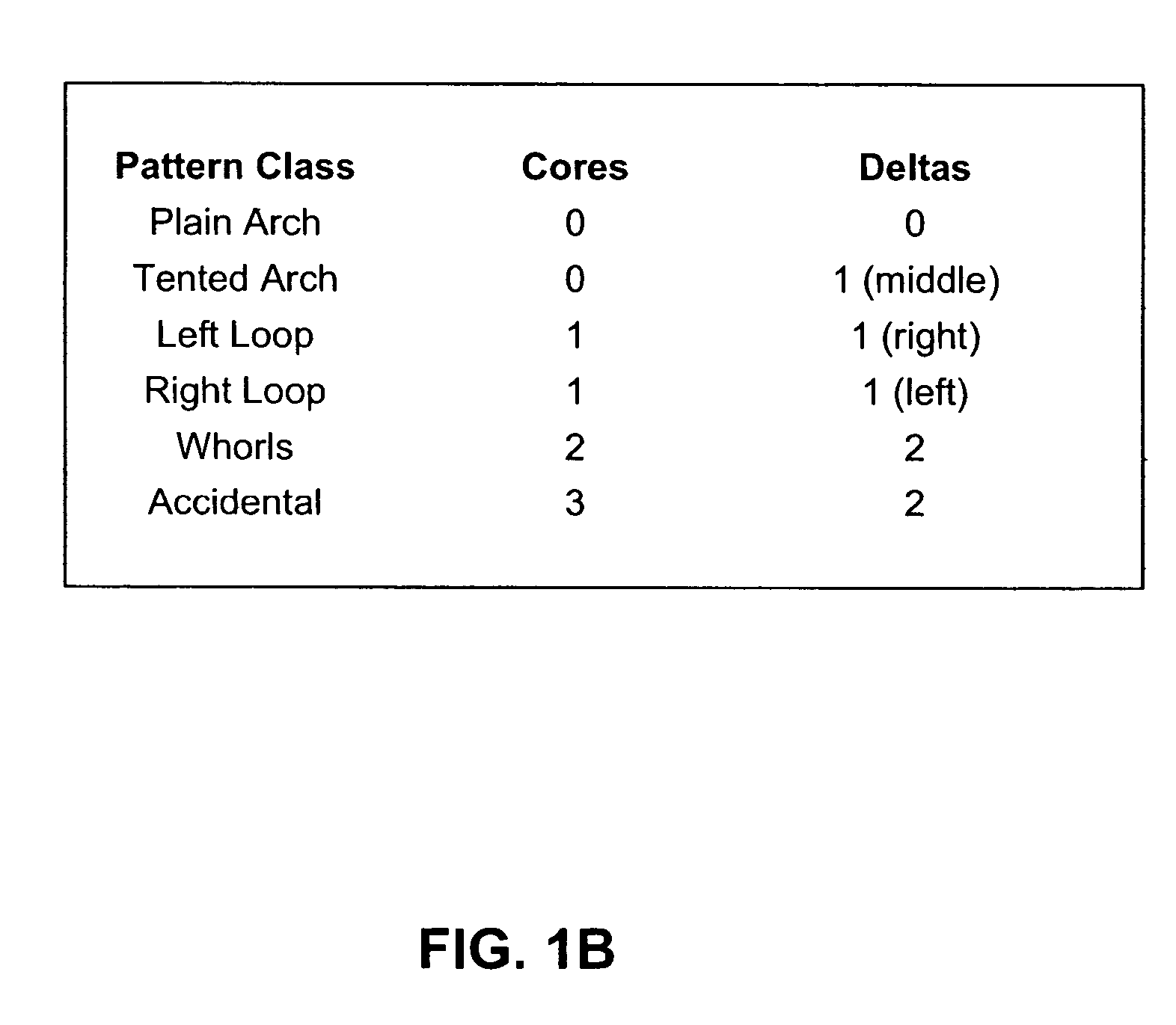
CROSS-REFERENCE TO RELATED APPLICATIONS [0001] This application claims the benefit of U.S. Provisional Application No. 60 / 484,324, filed Jul. 3, 2003, and incorporated in its entirety herein by reference.STATEMENT REGARDING FEDERALLY-SPONSORED RESEARCH AND DEVELOPMENT [0002] Not applicable. BACKGROUND [0003] 1Field of the Invention [0004] The present invention relates to print image analysis. [0005] 2. Related Art [0006] Fingerprints are often classified based on print characteristics, such as, the presence of a loop, arch, or whorl. Many classification methods are based on Henry classes which classify fingerprint images into arch, tented arch, left loop, right loop and whorl classes. FIG. 1A shows examples of print images corresponding to the respective arch, tented arch, left loop, right loop, whorl, and accidental classes. These classes are also called the global or high-level classes. These classifications are determined based on the position and type of singularity points calle...

Claims


Application Information

Patent Timeline
Patent Type & Authority Applications(United States)
IPC IPC(8): G06K9/00
CPCG06K9/0008G06V40/1359
Inventor DAVIS, PHILLIP SHAWN
Owner AUTHORIZER TECH INC
Learn More