Shock absorbing prosthetic foot for use with prosthetic ankle

a prosthetic foot and shock absorption technology, applied in the field of shock absorption prosthetic feet, can solve the problems of inability to use a prosthetic ankle, and large energy transferring designs, and achieve the effect of efficient energy transfer and enhanced stability

Inactive Publication Date: 2005-02-17
THE OHIO WILLOW WOOD CO INC
View PDF65 Cites 121 Cited by
  • Summary
  • Abstract
  • Description
  • Claims
  • Application Information

AI Technical Summary

Benefits of technology

[0002] The present invention is directed to a shock absorbing prosthetic foot that is able to absorb the shocks developed during ambulation with efficient energy transfer between heel strike and toe-off, while simultaneously enhancing stability. Certain embodiments of the shock absorbing foot of the present invention are designed for use with a prosthetic ankle, such as a multi-axis articulating prosthetic ankle.
[0006] Therefore, as can be seen, it is desirable to provide a prosthetic foot which is not subject to the shortcomings of the prior art. Consequently, the present invention is directed to a prosthetic foot that can absorb energy on heel strike and efficiently transfer the energy to the toe of the prosthesis for use during toe-off. Such a prosthetic foot of the present invention is also afforded with enhanced stability, control, function and durability. Particular embodiments of the present invention are designed for use with a prosthetic ankle.
[0008] Since the toe spring of the prosthetic foot according to this feature of the invention is connected between the foot plate and to the adapter element, it can efficiently transfer energy to the toe portion during toe-off.
[0009] According to another embodiment of the present invention, a prosthetic foot comprises an adapter element securable to a residual limb, a foot plate having a heel portion and a toe portion along the length thereof, and at least one toe spring connected between the adapter element and the toe portion of the foot plate, the toe spring comprising a curved leaf spring whose concave side exhibits a plurality of transverse ribs. The transverse ribs create a more constant stress spring, and effectively distribute the bending stresses along the length of the spring. This minimizes the risk of delamination of the toe spring and permits more efficient energy transfer during toe-off.
[0011] The further heel spring according to this embodiment of the present invention reduces loading at the socket of the prosthesis, and the non-extensible band limits the movement of the collar away from the heel during the rebound of the heel spring, thereby promoting efficient energy transfer to the toe spring for release during toe-off.

Problems solved by technology

As can be seen from the above-referenced prosthetic foot, known energy transferring designs can be quite bulky and inefficient.
Additionally, such prosthetic foot designs are not amenable to use with a prosthetic ankle due to their overall height.
More specifically, the height of such a prosthetic foot makes it impossible to use a prosthetic ankle, both because the location of a prosthetic ankle attached to such a foot would be too high, and because many amputees will not have an adequate amount of space available below their residual limbs.

Method used


Image

  • Shock absorbing prosthetic foot for use with prosthetic ankle
  • Shock absorbing prosthetic foot for use with prosthetic ankle
  • Shock absorbing prosthetic foot for use with prosthetic ankle

Examples


first embodiment

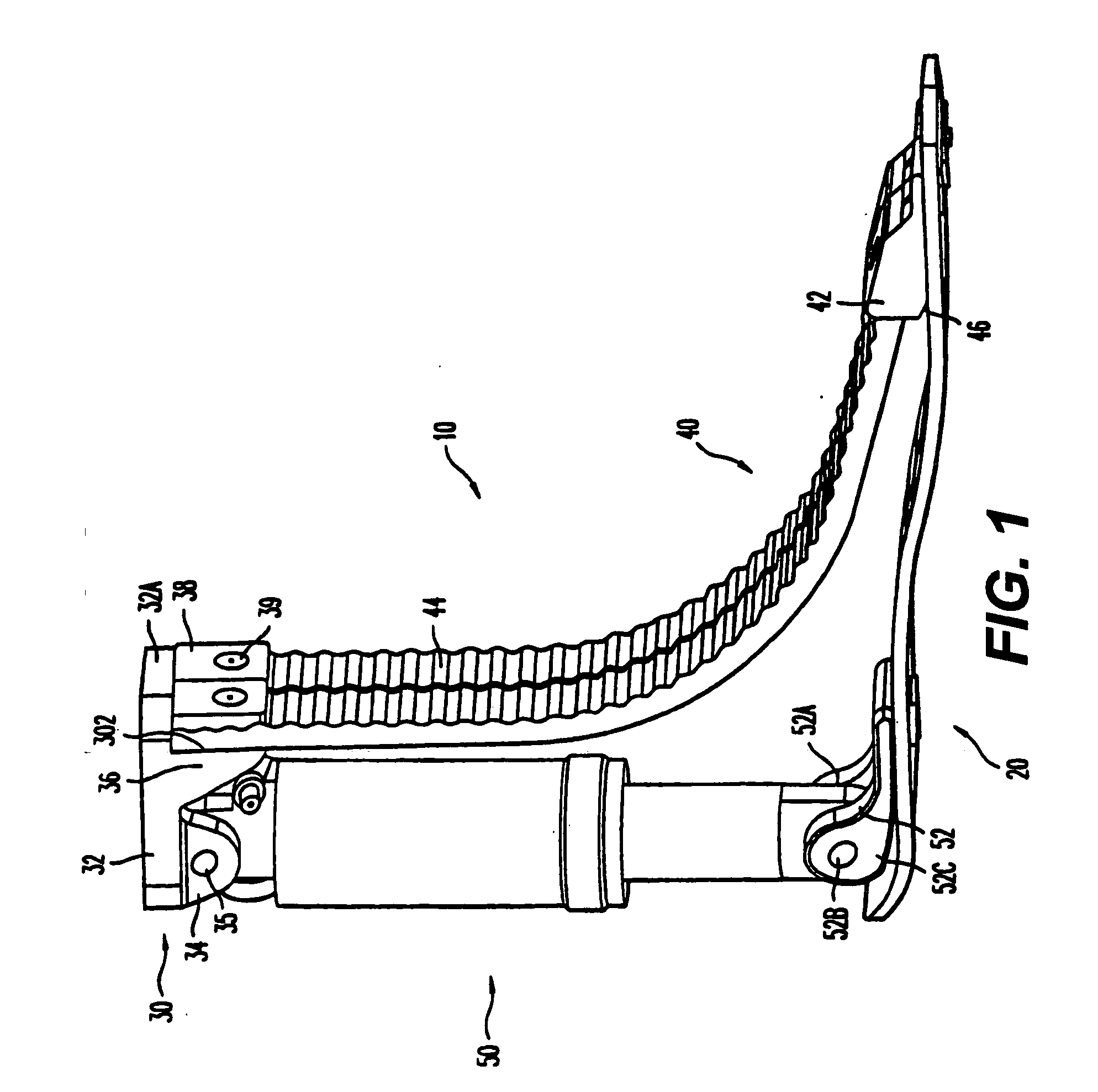
[0031] Referring now to the drawings wherein like reference numerals designate identical or corresponding parts throughout the several views, according to the invention illustrated in the non-limiting FIGS. 1 and 2 of the drawings, and in particular the variant of FIG. 1, the main components of a prosthetic foot 10 comprise contoured foot plate 20, a top adapter 30, a pair of toe springs 40 and a heel spring / shock absorber 50.

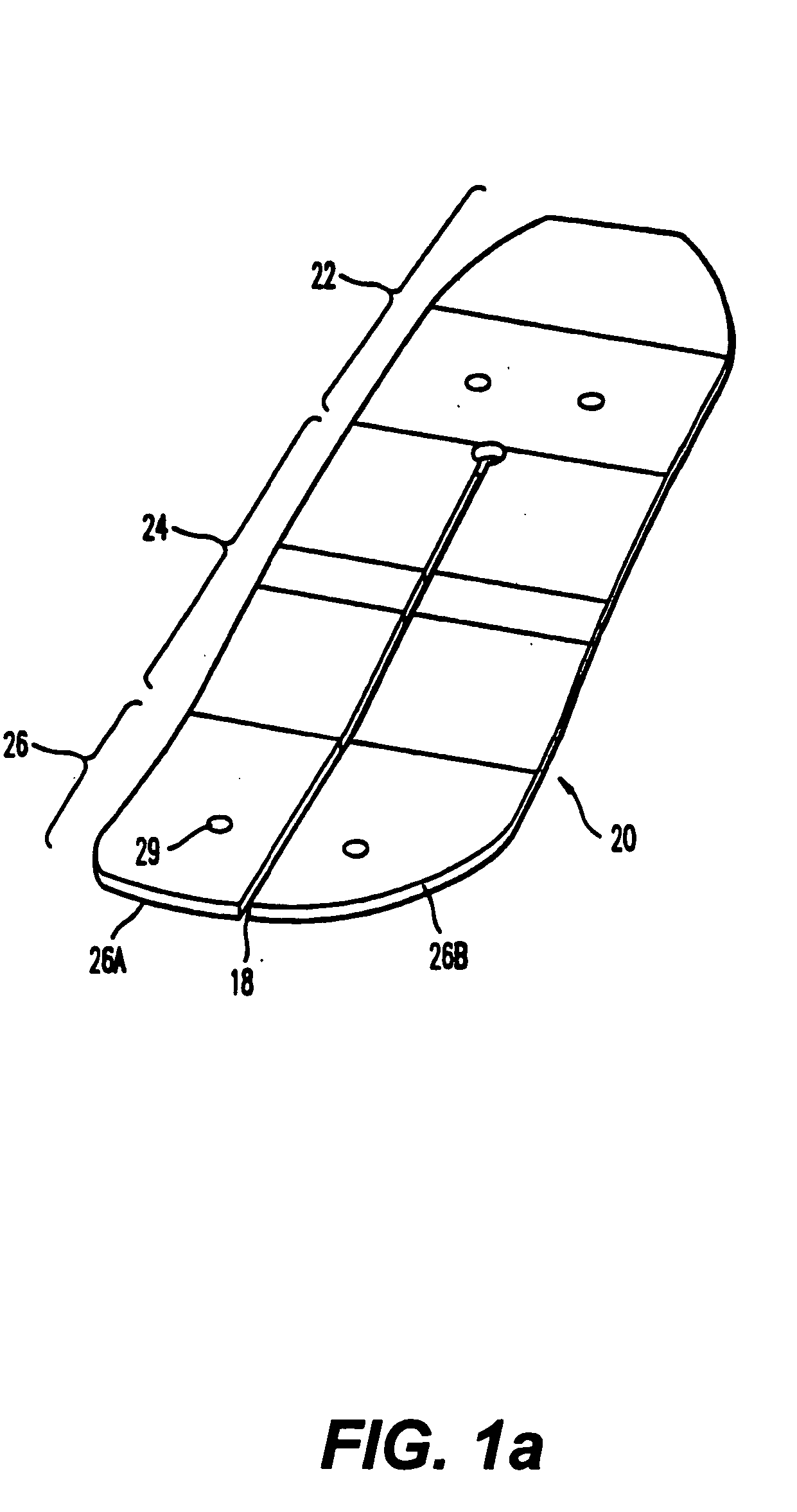
[0032] The contoured foot plate 20 is generally conventional and could be that disclosed in U.S. Pat. No. 4,865,612, except as set forth below. It includes a heel portion 22, an arch portion 24 and a ball portion 26 (FIG. 1a). A slot 28 may extend through the foot plate and longitudinally from the toe portion to the heel portion for all or part of the length of the foot plate, and thereby divide the toe portion into separate left and right toe parts 26A and 26B.

[0033] The foot plate is formed of a composite material which may be continuous carbon fibers in an ...

second embodiment

[0065] According to this embodiment, the top adapter 330 incorporates a collar 360 similar to that of the second embodiment, and which slides along a pylon 370. A heel spring 380 may be S-shaped and correspond to the further heel spring of the previous embodiment. As in the previous embodiment, a non-extensible band (not shown) limits the upward movement of the collar 360.

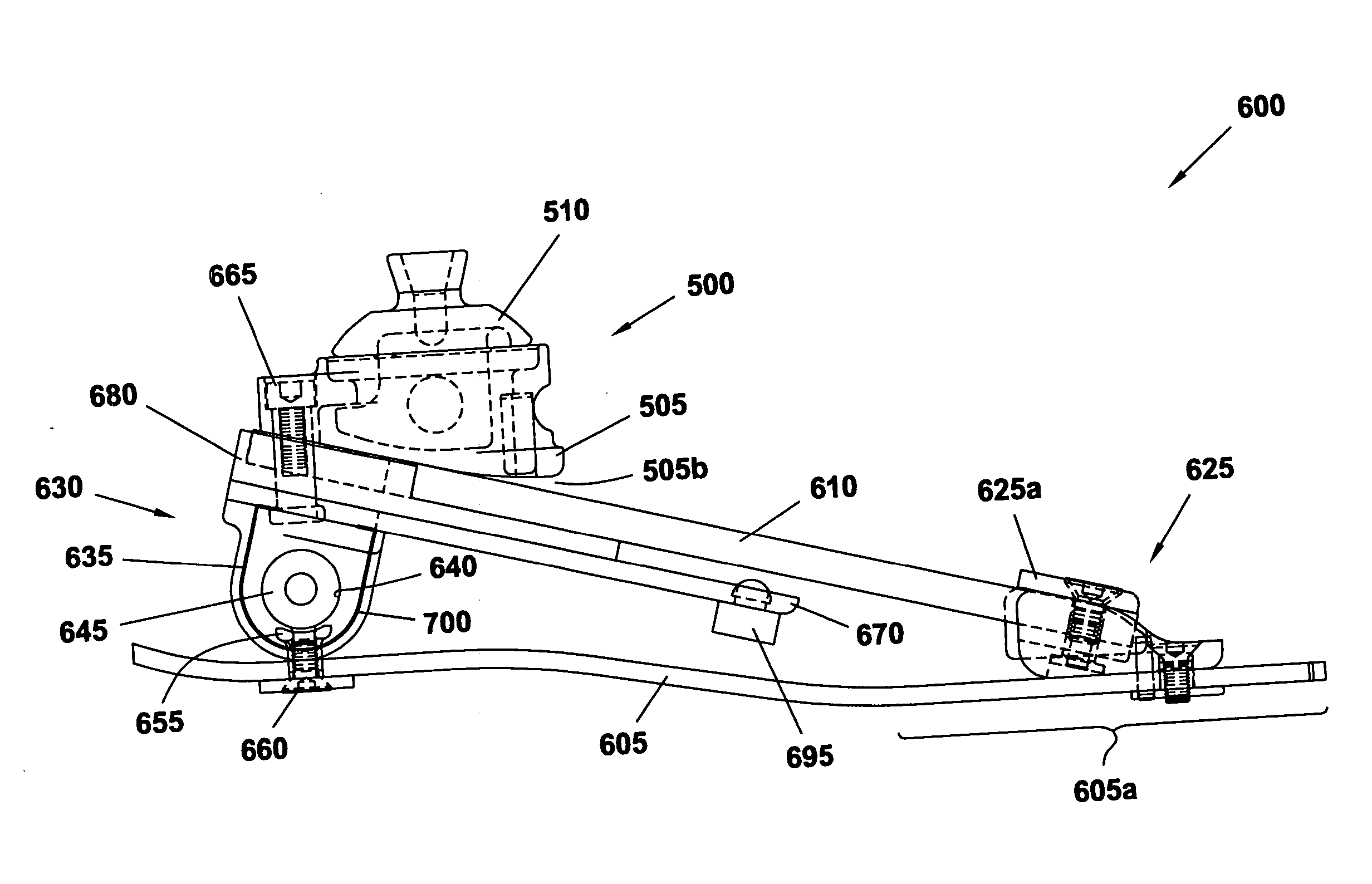
[0066] An alternate embodiment of a prosthetic foot 400 of the present invention can be observed in FIGS. 6-8. This embodiment of the prosthetic foot 400 is designed for use with a prosthetic ankle. Consequently, in order to allow for installation of the prosthetic ankle between the prosthetic foot 400 and a connecting portion of a prosthetic leg, this prosthetic foot has a lower profile than known prosthetic foot devices as well as the previously described exemplary prosthetic foot embodiments. Preferably, the prosthetic foot 400 is designed so that upon attachment of a prosthetic ankle thereto, the prosthetic ank...

embodiment 550

[0078] An alternate embodiment 550 of a prosthetic foot of the present invention is illustrated in FIGS. 9a-9c. Embodiments of this prosthetic foot 550 are substantially the same as embodiments of the prosthetic foot 400 shown in FIGS. 6-8, the exception being the addition of one or more auxiliary toe springs 560. When the prosthetic foot 550 utilizes a pair of (primary) toe springs 555, an auxiliary toe spring 560 is preferably provided to correspond to each primary toe spring. When the prosthetic foot 550 utilizes a single primary toe spring 555, one, or a pair, of auxiliary toe springs 560 may be provided. The primary toe springs 555 of this embodiment may be the same as the (primary) toe springs 410 of FIGS. 6-8.

[0079] The auxiliary toe spring 560 may be constructed in a similar manner to the toe springs 410 described previously. The spring force produced by the auxiliary toe spring 560 may be similar to, or different than, the spring force provided by the primary toe spring 555...


PUM


Abstract

A low profile prosthetic foot designed for use with a prosthetic ankle. The prosthetic foot includes at least one toe spring and at least one heel spring. The prosthetic foot is able to absorb shocks generated during ambulation of a user of said foot. When a prosthetic ankle is attached to the prosthetic foot, the position (height) of the ankle preferably approximates the position (height) of a typical human ankle.

Description

[0001] The present application is a continuation-in-part of U.S. application Ser. No. 10 / 352,902, filed on Jan. 29, 2003, which is a continuation of U.S. application Ser. No. 09 / 502,455, filed on Feb. 11, 2000, and now U.S. Pat. No. 6,602,295, which is based on Provisional Application No. 60 / 135,704, filed on May 5, 1999.BACKGROUND AND SUMMARY OF THE INVENTION [0002] The present invention is directed to a shock absorbing prosthetic foot that is able to absorb the shocks developed during ambulation with efficient energy transfer between heel strike and toe-off, while simultaneously enhancing stability. Certain embodiments of the shock absorbing foot of the present invention are designed for use with a prosthetic ankle, such as a multi-axis articulating prosthetic ankle. [0003] Specialized prosthetic feet have recently been developed in an effort to satisfy the specialized needs of different amputees. For example, active amputees who engage in sports or other strenuous physical activi...

Claims


Application Information

Patent Timeline
Patent Type & Authority Applications(United States)
IPC IPC(8): A61F2/50A61F2/66
CPCA61F2/66A61F2002/5003A61F2002/6657A61F2002/5079A61F2002/5072
Inventor DODDROE, JEFFREY L.ARBOGAST, ROBERT E.COLVIN, JAMES M.CAPPER, JAMES W.
Owner THE OHIO WILLOW WOOD CO INC
Why Eureka
Try Eureka