

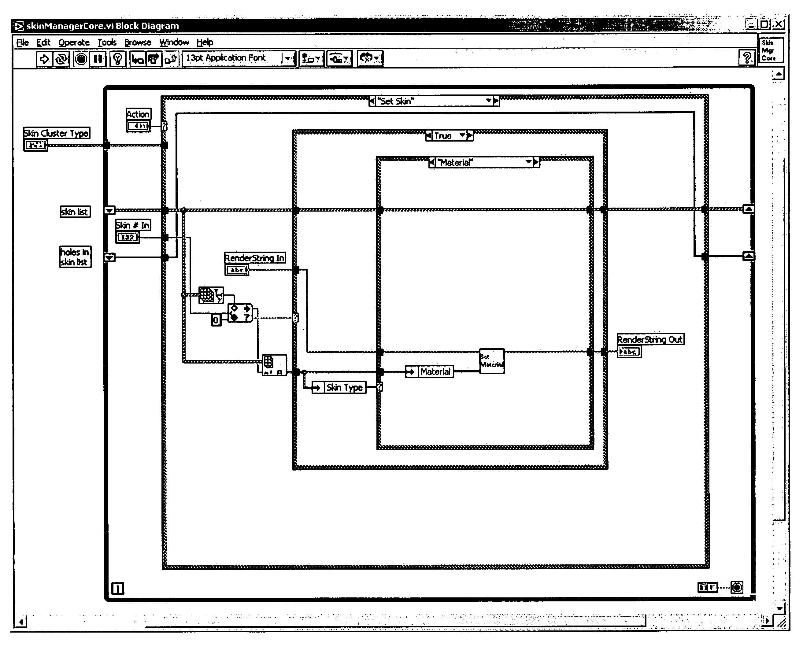
Graphical programming system and method for creating and managing a scene graph
a technology of scene graph and programming system, which is applied in the field of system and method for creating a scene graph, can solve the problems of user programming skills and ability to interact with the computer system, which often become a limiting factor in the achievement of optimal utilization of the computer system, and the task of programming a computer system to model or implement a process is often further complicated and user is often not fully proficient in techniques
- Summary
- Abstract
- Description
- Claims
- Application Information
AI Technical Summary
Benefits of technology
Problems solved by technology
Method used
Image

Examples
Embodiment Construction
[0049] Incorporation by Reference
[0050] The following references are hereby incorporated by reference in their entirety as though fully and completely set forth herein:
[0051] U.S. Provisional Application Ser. No. 60 / 494,732 titled “Graphical Programming System and Method for Creating and Managing A Scene Graph” filed Aug. 13, 2003.
[0052] U.S. Pat. No. 4,914,568 titled “Graphical System for Modeling a Process and Associated Method,” issued on Apr. 3, 1990.
[0053] U.S. Pat. No. 5,481,741 titled “Method and Apparatus for Providing Attribute Nodes in a Graphical Data Flow Environment”.
[0054] U.S. Pat. No. 5,504,917 titled “Method and Apparatus for Providing Picture Generation and Control Features in a Graphical Data Flow Environment”, filed Jan. 14, 1994.
[0055] U.S. Pat. No. 6,173,438 titled “Embedded Graphical Programming System” filed Aug. 18, 1997.
[0056] U.S. Pat. No. 6,219,628 titled “System and Method for Configuring an Instrument to Perform Measurement Functions Utilizing Co...
PUM
 Abstract
Description
Claims
Application Information