

Continuous reactive power support for wind turbine generators
a technology of reactive power support and wind turbine generator, which is applied in the direction of electric generator control, machine/engine, dynamo-electric converter control, etc., can solve the problems of raising voltage, putting undue stress on transmission lines, transformers and other electrical components
- Summary
- Abstract
- Description
- Claims
- Application Information
AI Technical Summary
Problems solved by technology
Method used
Image

Examples
Embodiment Construction
In the following description, for purposes of explanation, numerous specific details are set forth in order to provide a thorough understanding of the invention. It will be apparent, however, to one skilled in the art that the invention can be practiced without these specific details. In other instances, structures and devices are shown in block diagram form in order to avoid obscuring the invention.
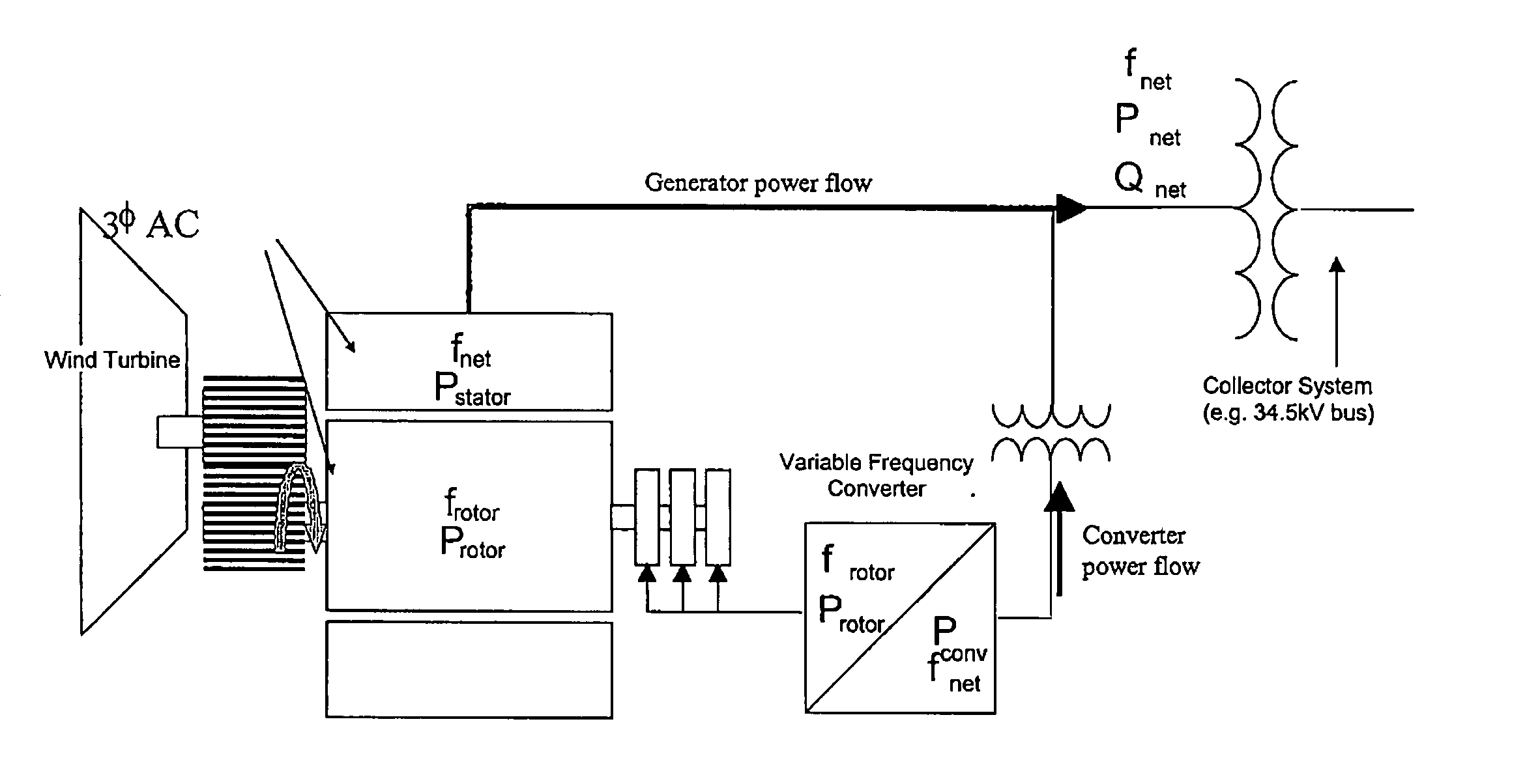
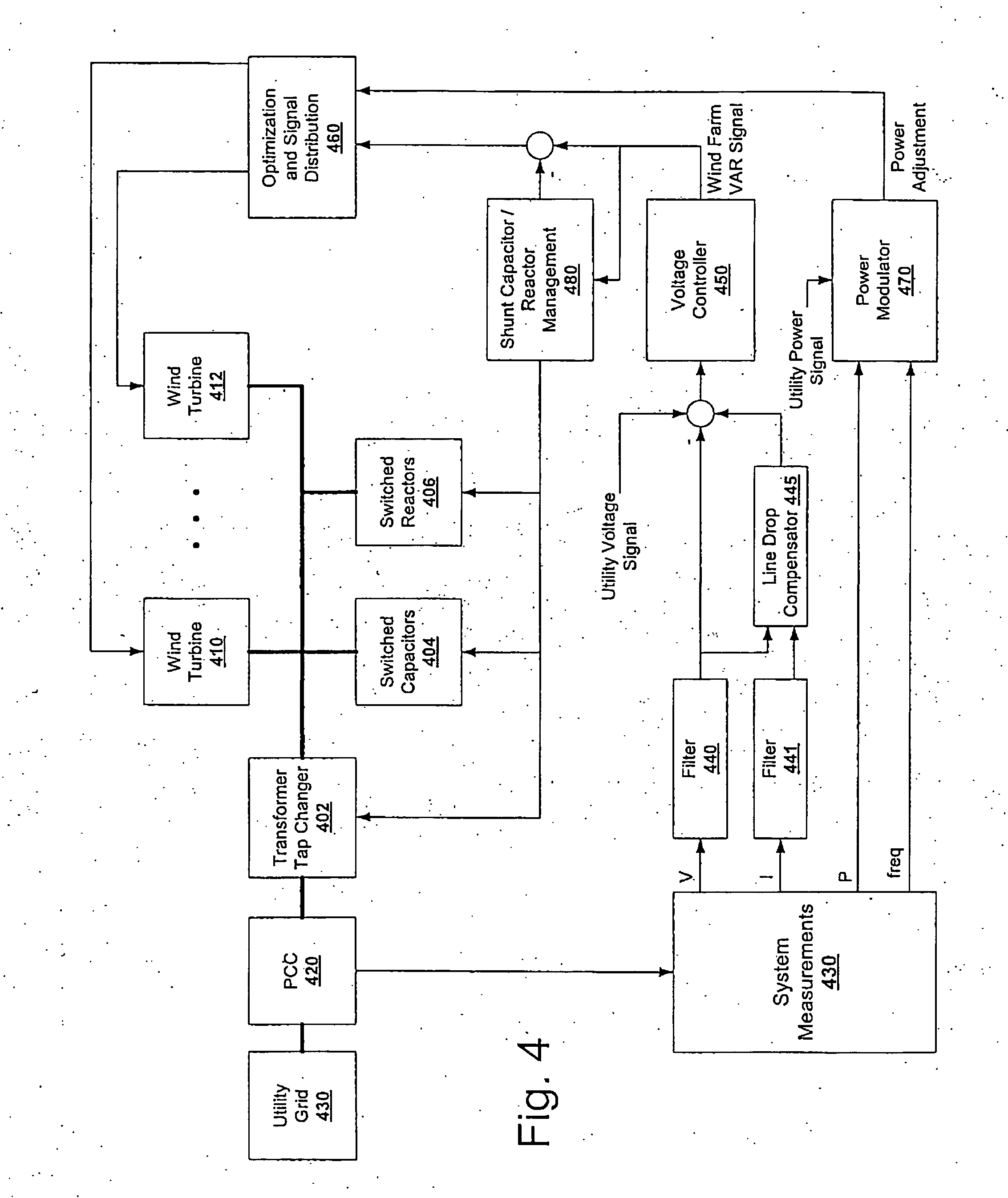
The technique described herein provides the potential to utilize the total capacity of a wind turbine generator system (i.e., a wind farm) to provide dynamic VAR (reactive power support). The VAR support provided by individual wind turbine generators in a system can be dynamically varied to suit application parameters.
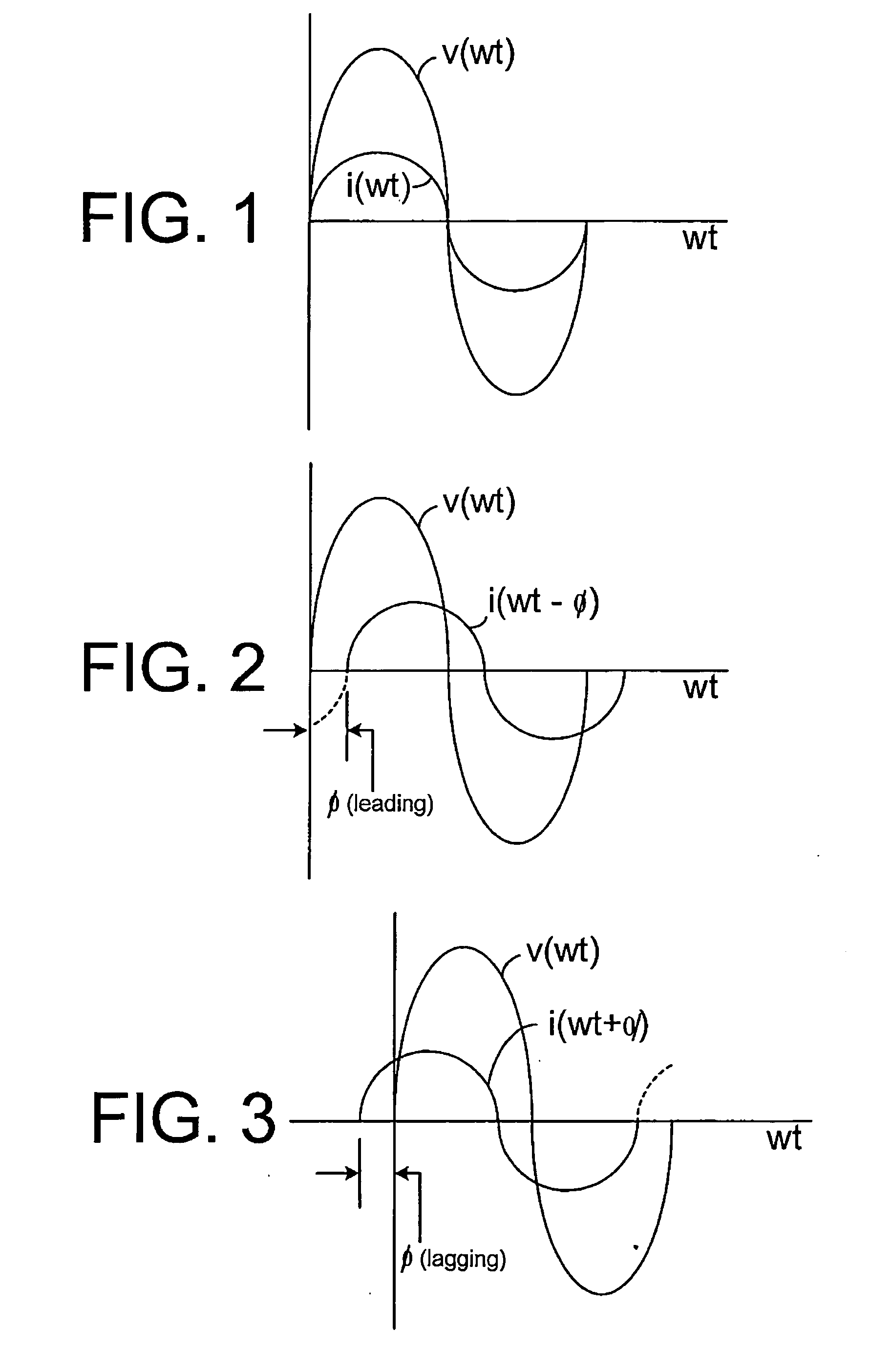
Wind turbine generators can provide VAR support based on real power generation and power factor. This type of VAR support can be described, for example, by the equation:
VAR=Watt* tan (θ)
where θ is the power factor angle. Power factor control has some shortcomings. Be...
PUM
 Abstract
Description
Claims
Application Information