Quick-release clamp for photographic equipment

a technology for mounting equipment and photographic equipment, which is applied in the direction of instruments, stands/trestles, camera body details, etc., can solve the problems of insufficient time for screwing the camera body or lens to the tripod, method takes an appreciable amount of time, and requires car

Active Publication Date: 2005-02-24
REALLY RIGHT STUFF
View PDF4 Cites 128 Cited by
  • Summary
  • Abstract
  • Description
  • Claims
  • Application Information

AI Technical Summary

Problems solved by technology

These methods take an appreciable amount of time and require care to ensure that the threads of the stud are properly aligned with the threads in the socket.
Further, there is often insufficient time to screw the camera body or lens to the tripod before a particular shot should be taken.
This lack of time requires that the camera either be held in-hand, potentially resulting in image blur from the shake of the hand, or that the shot be missed altogether.
Unfortunately, existing quick-release clamps have certain disadvantages.
This outward force tends to likewise push the lever away from the first, locking position, thus loosening the fitting be

Method used


Image

  • Quick-release clamp for photographic equipment
  • Quick-release clamp for photographic equipment
  • Quick-release clamp for photographic equipment

Examples


Embodiment Construction

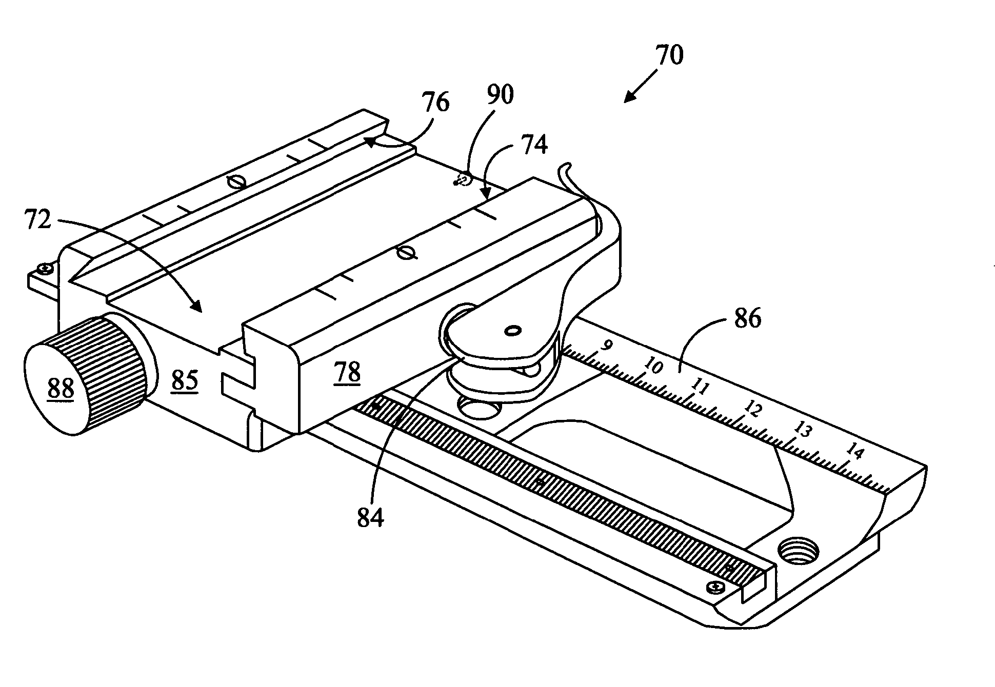
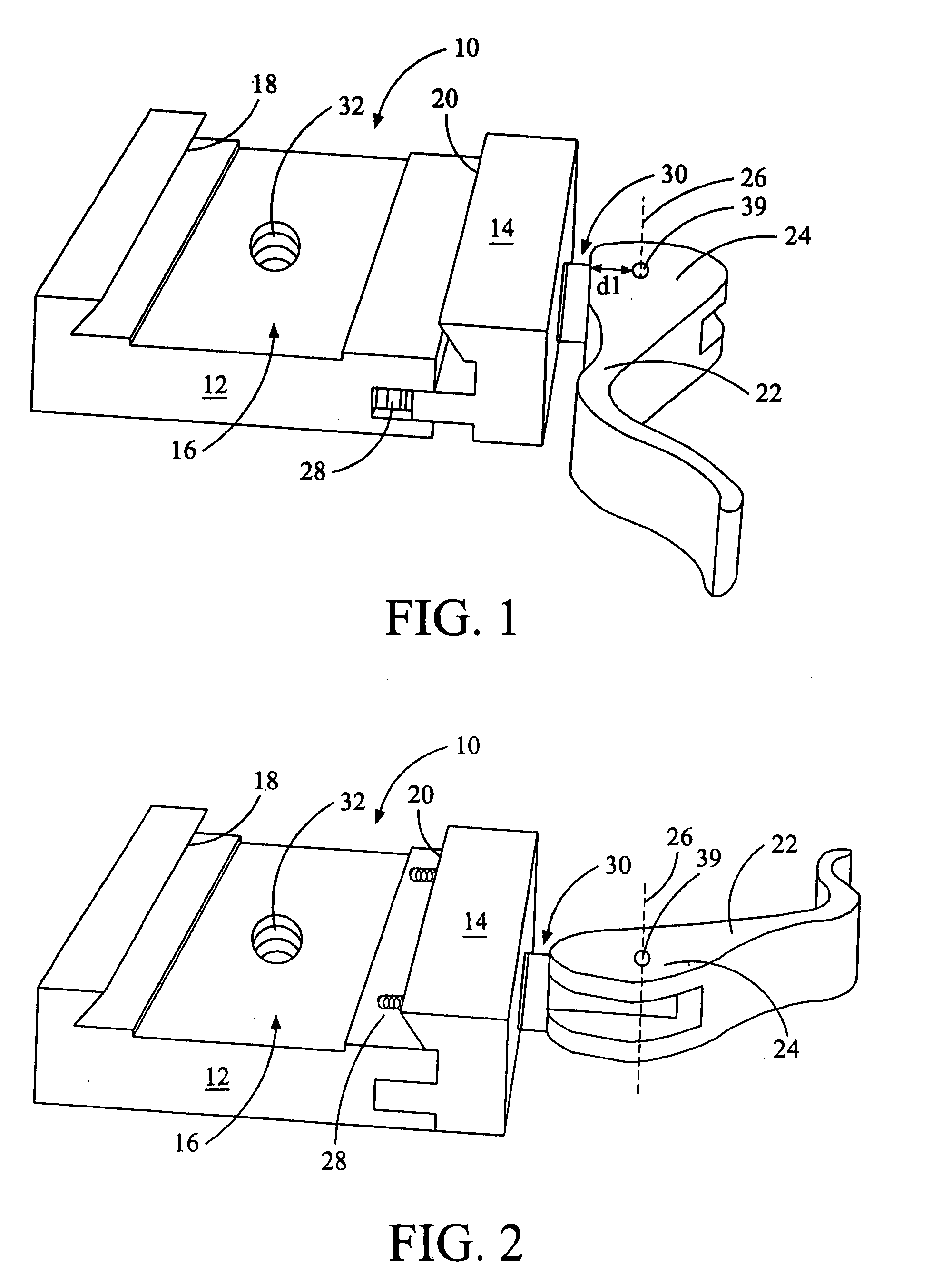
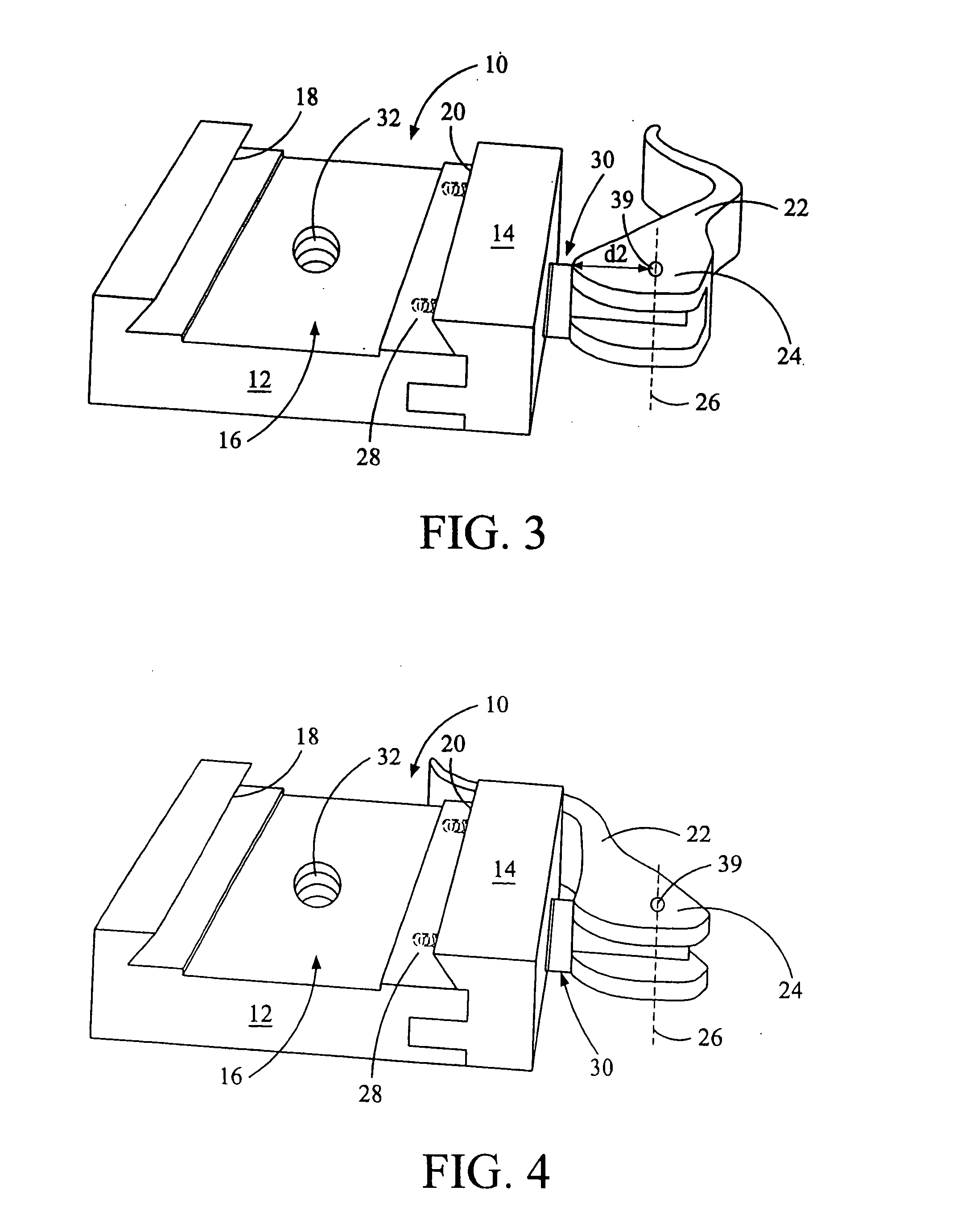
[0022]FIG. 1 shows a clamp 10 that comprises a body 12 and an adjustable arm 14 (shown in FIGS. 10A-10E) that together form a channel 16 having opposed side walls 18 and 20. The body 12 may define an opening 32 through which the clamp 10 may be secured to the upper portion of a tripod or other support. The adjustable arm 14 is slidably engaged along the cantilevered portion 59 of a stud 36 (shown in FIGS. 6, 7, and 9A-9C) securely mounted in the body 12, as shown in FIG. 11. Movement of the adjustable arm 14 selectively adjusts the width of the channel 16 and is accomplished through manual operation of a lever 22 fastened to the distal end 60 of the stud 36. The lever 22, attached to the adjustable arm 14, permits quick adjustment of the spacing between the side walls 18 and 20 so that the channel 16 may selectively either grip or release a pair of rails attached to the base of a camera body (not shown). Each respective side wall 18 and 20 is preferably angled upward and inward to f...


PUM


Abstract

A clamp for securely mounting photographic equipment to a support, such as a tripod.

Description

CROSS REFERENCE TO RELATED APPLICATIONS [0001] This application is a continuation-in-part of U.S. patent application Ser. No. 10 / 645,419, filed Aug. 20, 2003.BACKGROUND OF THE INVENTION [0002] The present invention relates to a clamp for mounting photographic equipment to a support, such as a tripod or ball head. [0003] Photographic equipment may be mounted to a camera stand in a variety of ways. Some camera bodies, for example, have threaded sockets in their base so they can be directly mounted to a bolt that extends upwardly from the support. The camera body is positioned over the support so that the bolt fits within the socket and the camera body is spun around several times to screw the camera body to the support. Alternatively, and particularly when a heavy, elongate camera lens is attached to a camera body, the camera lens will include a support having a threaded socket positioned below the lens so that the lens may be mounted to the support in the same manner as a camera body...

Claims


Application Information

Patent Timeline
IPC IPC(8): F16M11/04G03B17/56
CPCF16M11/04F16M11/041G03B17/56F16M13/00F16M2200/027F16M11/16G03B17/566
Inventor JOHNSON, JOSEPH M.
Owner REALLY RIGHT STUFF
Why Eureka
Try Eureka