

Golf ball
a golf ball and aerodynamic technology, applied in the field of golf balls, can solve the problems of adversely affecting the aerodynamic properties of golf balls, and achieve the effect of excellent appearan
Inactive Publication Date: 2005-03-03
DUNLOP SPORTS CO LTD
View PDF5 Cites 27 Cited by
- Summary
- Abstract
- Description
- Claims
- Application Information
AI Technical Summary
Benefits of technology
A method of the production of a golf ball according to the present invention comprises: a molding step in which a ball body having dimples with a size in the meridional direction being greater than a size in the meridional direction, in the vicinity of the equatorial line, is formed with a mold; and a removing step in which a flash generated on a seam resulting from the mold is removed along with reduction of a size in the latitudinal direction of the dimple, through grinding the vicinity of the equatorial line. According to this method of the production, the dimples come to have a suitable shape on behalf of the deformation accompanied by grinding of the flash. The golf ball obtained according to this procedure is excellent in appearance.
Problems solved by technology
The deformation may adversely affect the aerodynamic properties of the golf ball 8.
Method used
View moreImage
Smart ImageViewing Examples

Examples
example 1
A mold having upper and lower mold half each having a hemispherical cavity and 8 pimples was provided. To this mold was placed a spherical core followed by injection of a molten resin between this core and the cavity face to form a cover. On behalf of the pimples, dimples having the specifications as presented in Table 1 below were formed. A flash generated on the seam of thus resulting ball body was cut away with a sand belt. Paint was applied on this ball body to give a golf ball.
Login to View More PUM
| Property | Measurement | Unit |
|---|---|---|
| Angle | aaaaa | aaaaa |
| Angle | aaaaa | aaaaa |
| Size | aaaaa | aaaaa |
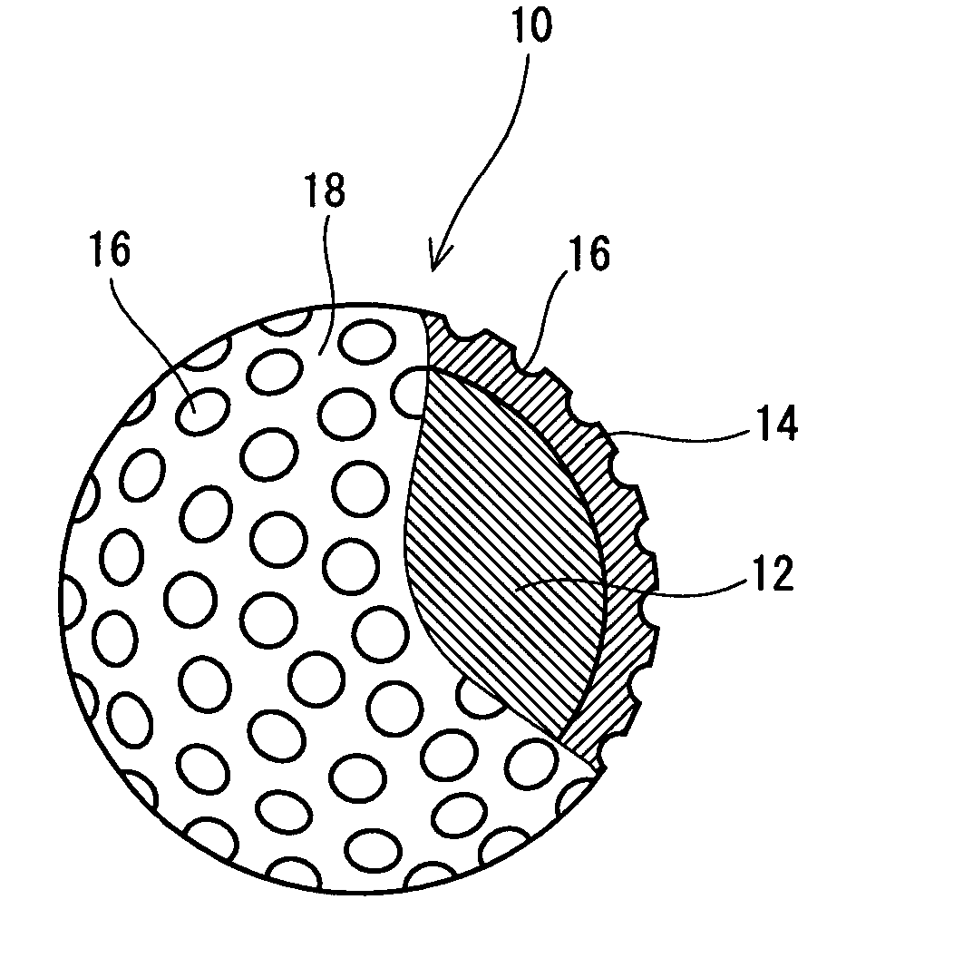
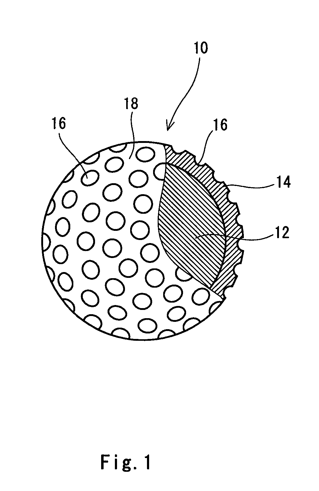
Abstract
A ball body is formed with a mold having upper and lower mold half. Dimples 16 having a shape inverted from the shape of the pimples of the mold are formed on the ball body. The dimples 16 in the vicinity of the equatorial line have a size in the meridional direction D1 being greater than a size in the latitudinal direction D2. The difference between the size in the meridional direction D1 and the size in the latitudinal direction D2 is 0.01 mm or greater and 0.50 mm or less. By grinding the ball body in the vicinity of the equatorial line, a flash generated on the seam resulting form the mold is removed. According to the grinding, the size in the meridional direction of the dimple 16 is reduced, and thus, plane shape of the dimple becomes closer to a perfect circle.
Description
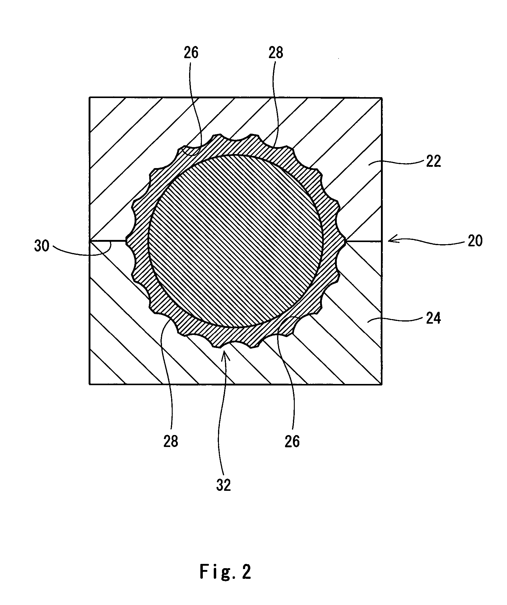
This application claims priority on Patent Application No. 2003-306309 filed in Japan on Aug. 29, 2003. BACKGROUND OF THE INVENTION 1. Field of the Invention The present invention relates to method of the production of a golf ball having dimples on the surface thereof. 2. Description of the Related Art For the formation of a golf ball, injection molding or compression molding has been employed. In either case, a mold having upper and lower mold half having a hemispheric cavity is used. Upon formation, material for the molding leaks outside from the parting line between the upper and lower mold half. Due to this leakage, a ring-shaped flash is generated in the part corresponding to the parting line (hereinafter, referred to as “seam”) on the surface of the ball body. Although a gate is provided on the parting line of the mold for the injection molding, a flash is also generated in the part corresponding to this gate. These flashes need to be removed. The flash is removed by bri...
Claims
Login to View More Application Information
Patent Timeline
 IPC IPC(8): A63B37/04A63B45/00A63B37/00B29C37/02
CPCA63B37/0004B29C37/02B29L2031/54A63B37/0008A63B37/0009A63B37/0012A63B45/00A63B37/0007
InventorENDO, SEIICHIROSAJIMA, TAKAHIRO
OwnerDUNLOP SPORTS CO LTD