Adjuster for elevated floor

a technology for adjusting devices and floors, applied in the direction of screws, threaded fasteners, mechanical equipment, etc., can solve the problems of inability to reduce the floor, inconvenient adjustment for use of the floor, and waste of spa

Inactive Publication Date: 2005-03-10
CHEN YAO CHUNG +1
View PDF15 Cites 24 Cited by
  • Summary
  • Abstract
  • Description
  • Claims
  • Application Information

AI Technical Summary

Benefits of technology

[0011] To get the above stated objects, an adjuster for an elevated floor of the present invention is disposed for connected with a connecting hole which is on the elevated floor. The adjuster comprises a threaded pipe, a footing seat and a fixing screw, wherein the threaded pipe has an inner thread for connecting with the connecting hole which is on the elevated floor. The footing seat has an external thread on an external upper end thereof for threading and connecting into said threaded pipe, and further has an adjustment hole on its upper end. The fixing screw is mounted above the footing seat and is thread connected into the threaded pipe, rotation of the screw can press tight the footing seat, the fixing screw has a through hole extended from top to bottom, which is larger than the adjustment hole of the footing seat, so that the adjustment tool can be extended through the through hole and inlaid in the adjustment hole for adjusting the displacement of the threaded pipe relative to the footing seat.

Problems solved by technology

Therefore, at the initial of construction of an office building, pipelines are embedded in advance; however, the initial planning often is unable to meet the requirement of continuous extension of pipelines afterwards, and pipelines are differently required in different arts.
The floor itself has a thickness of about 3 cm, plus the footing seat and the fixing nut beneath the footing seat (about 1.5 cm), an elevated floor after assembling will have a height of at least 6 to 10 cm, and this is the maximum limitation of such elevated floor in assembling and production presently; for a new building preserved with larger heights in space, it will not result a too large problem in space; but for an old building with lower indoor heights originally, it will result waste of space in that the indoor heights will be reduced to make feeling of oppression.
According to the above stated causes, the height after assembling of the conventional elevated floor is unable to reduce, and adjusting for use of the floor will be quite inconvenient.

Method used


Image

  • Adjuster for elevated floor
  • Adjuster for elevated floor
  • Adjuster for elevated floor

Examples


Embodiment Construction

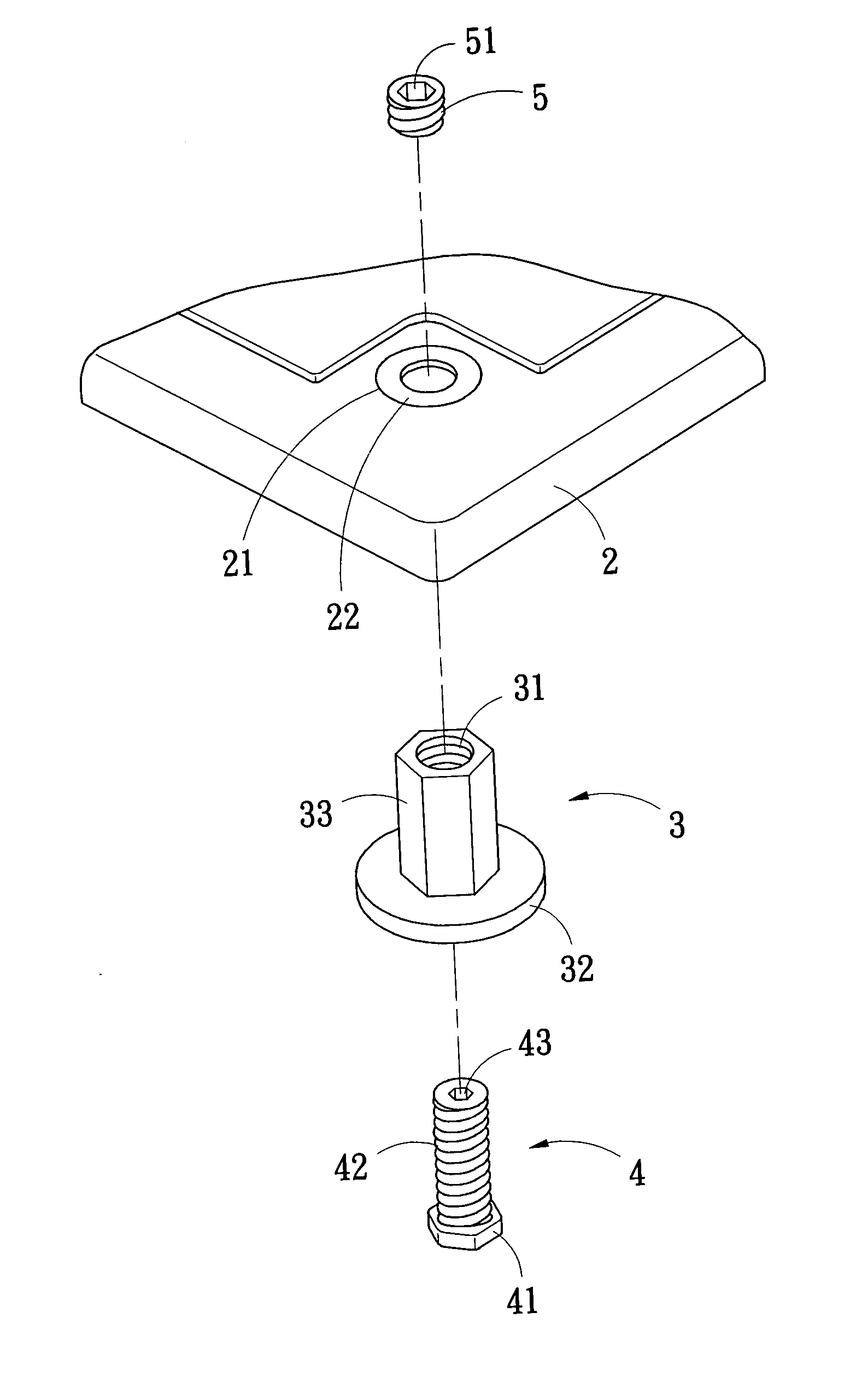
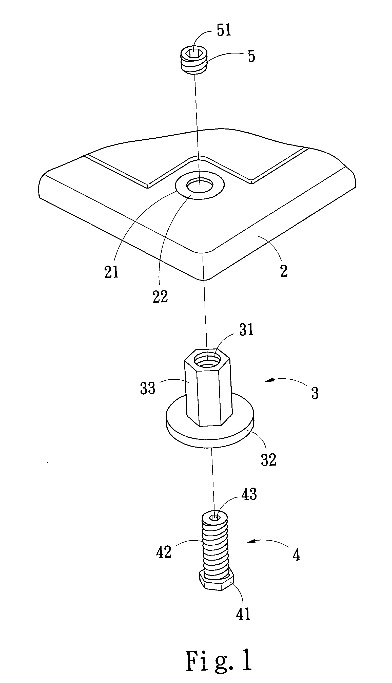
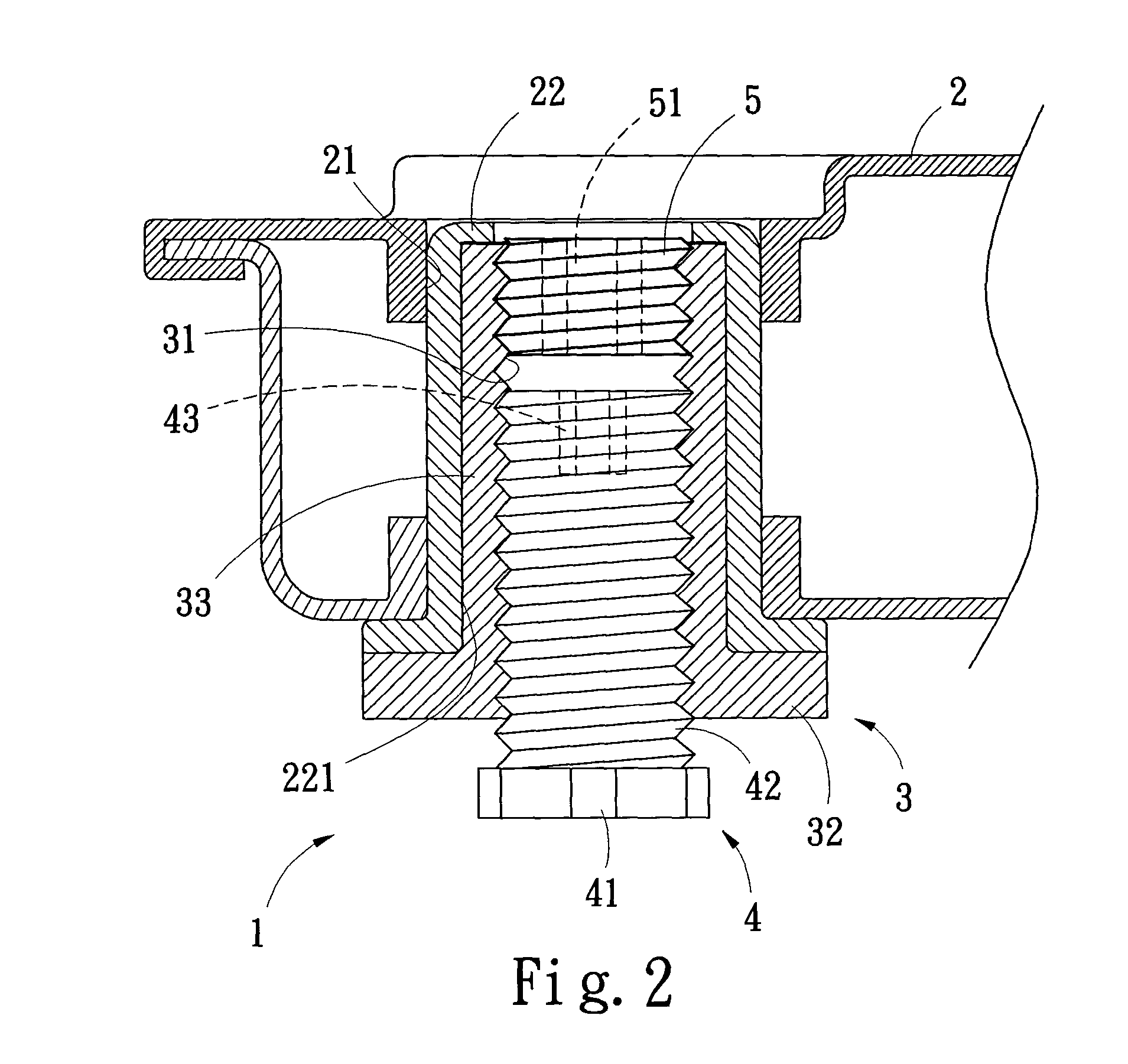
[0019] Referring firstly to FIGS. 1 and 2 showing a preferred embodiment of an adjuster 1 for an elevated floor 2 of the present invention, the adjuster 1 is connected with a connecting hole 21 provided on the elevated floor 2. It comprises mainly: a threaded pipe 3, a footing seat 4 and a fixing screw 5.

[0020] A bush 22 is provided between the threaded pipe 3 and the connecting hole 21 on the elevated floor 2, and has an inner hexagonal hole 221. The threaded pipe 3 is in the form of an inversed “T” and has an inner thread 31, and has on the bottom end thereof a circular base 32. The upper portion of the threaded pipe 3 is a hexagonal stub 33 for connecting with the inner hexagonal hole 221 of the bush 22.

[0021] The footing seat 4 has a base 41 for standing on the ground, the footing seat 4 is provided on the external upper end thereof with an external thread 42 for threading and connecting with the threaded pipe 3, and the footing seat 4 further has an hexagonal adjustment hole ...


PUM


Abstract

An adjuster for an elevated floor comprises a threaded pipe having an inner thread for connecting with a connecting hole which is on the elevated floor, and the threaded pipe is thread connected therein with a footing seat and a fixing screw mounted above the footing seat. The footing seat has an adjustment hole on its upper end, the fixing screw has a through hole extended from top to bottom, which is larger than the adjustment hole of the footing seat, so that the adjustment tool can be extended through the through hole and inlaid in the adjustment hole for adjusting the displacement of the threaded pipe relative to the footing seat. The adjuster can effectively reduce the gross height of the elevated floor and reduce waste of space. Further, it is suitable for use in new and old buildings.

Description

BACKGROUND OF THE INVENTION [0001] 1. Field of the Invention [0002] The present invention is related to an adjuster for an elevated floor, and especially to such an adjuster for an elevated floor that can lower the height of an assembled elevated floor, and can adjust the height of the elevated floor above the latter; it has a wide range of application, and can reduce waste of space, it is suitable for use in novel and used spaces of offices. [0003] 2. Description of the Prior Art [0004] Following advance of science and technology, people contact more and more lines for use; particularly in office buildings, various lines (such as networks and cables) are arranged in a mutually crossing and gathering mode. Therefore, at the initial of construction of an office building, pipelines are embedded in advance; however, the initial planning often is unable to meet the requirement of continuous extension of pipelines afterwards, and pipelines are differently required in different arts. [000...

Claims


Application Information

Patent Timeline
Patent Type & Authority Applications(United States)
IPC IPC(8): E04F15/024F16B5/02F16B35/04
CPCE04F15/02476F16B35/045F16B5/0233
Inventor CHEN, YAO-CHUNGWANG, SHIH-JAN
Owner CHEN YAO CHUNG
Why Eureka
Try Eureka