Nasal and oral cannula apnea detection device

a detection device and cannula technology, applied in the field of cannulas, can solve the problems of marginal effectiveness and reduced patient comfor

Inactive Publication Date: 2005-03-10
PRO TECH SERVICES A WASHINGTON CORP
View PDF10 Cites 206 Cited by
  • Summary
  • Abstract
  • Description
  • Claims
  • Application Information

AI Technical Summary

Problems solved by technology

The greatest challenge in this design (and the most unique aspect) is the capture of the oral flow signal, particularly the inspiratory oral flow signal.
These designs reduce patient comfort due to their bulk and are only marginally effective.

Method used


Image

  • Nasal and oral cannula apnea detection device
  • Nasal and oral cannula apnea detection device
  • Nasal and oral cannula apnea detection device

Examples


Embodiment Construction

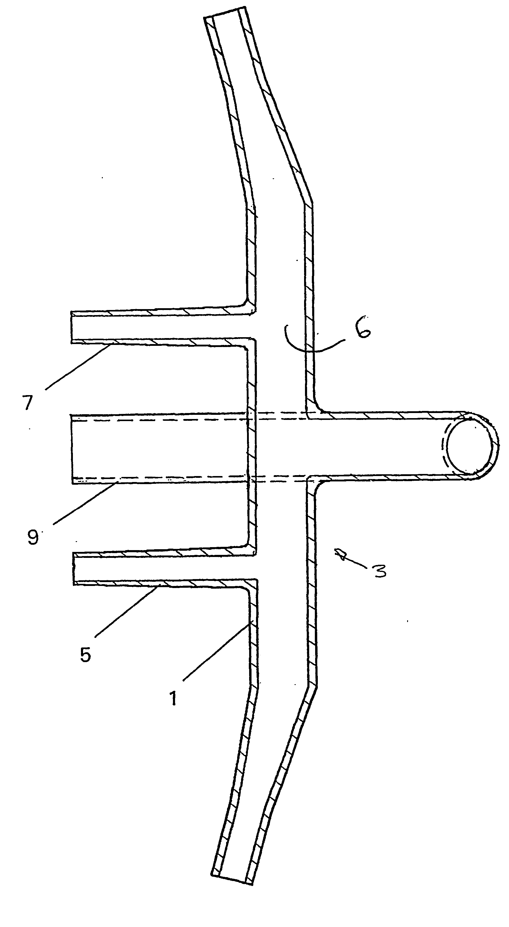
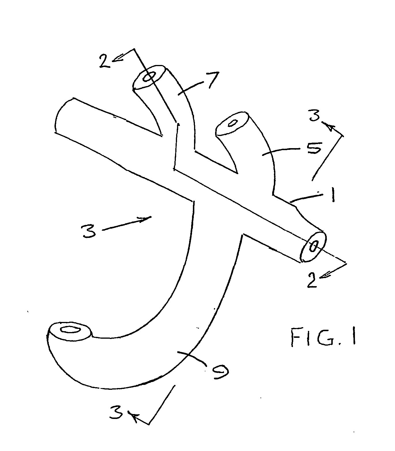
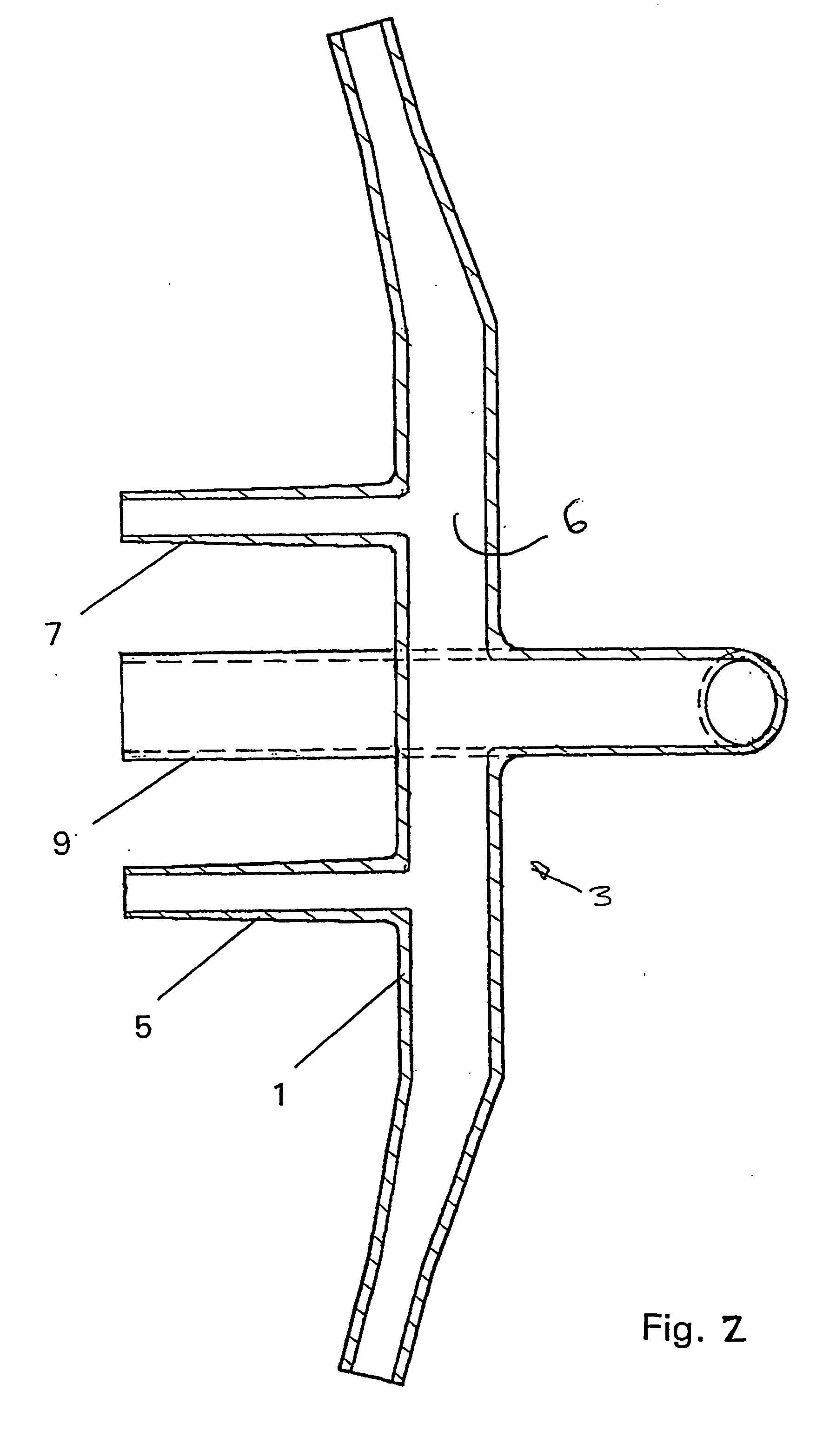
[0019] Referring to FIGS. 1 and 2, a cannula 3 comprises a main body 1, having an internal passage 6, which supports a pair of nares 5, 7 and a mouthpiece, oral prong, or inlet tube 9. The cannula 3 is composed of polyvinyl chloride (PVC).

[0020] Referring now to FIG. 3 the mouthpiece 9 defines a straight portion 18 adjacent the main body of the cannula 3 which, in early prototypes, had a length from the center of the main body 1 of about 0.250 inches. It appears from later examples, however, that a shorter straight portion 18 having a length of about 0.200 inches from the center of the main body or less may provide superior performance.

[0021] The cannula makes use of the natural funneling effect of the lips and mouth opening to produce a superior signal. FIG. 4 illustrates the inspiratory airflow 10. The surrounding air is funneled into the oral opening 11 between the lips 12, 13 and into the upper airway. The velocity of the airflow is somewhat higher over the surface of the lips...


PUM


Abstract

A cannula (3) defined by a main body (1) having an internal passage (6). The internal passage (6) communicate with a nare (5, 7) and an oral prong or a mouthpiece (9) which is adjustable to provide a desirable signal from a patient's mouth and nose to indicate breathing by the patient.

Description

[0001] This invention provides a novel cannula suitable for use in both nasal and oral applications, and a method of use thereof. BACKGROUND OF THE INVENTION [0002] This invention relates generally to cannulas adapted for both mouth and nasal use to monitor breathing, in particular, a method of manufacturing a cannula adapted to interconnect with both nasal passages and the mouth for use to monitor breathing, especially for the detection of apnea (the absence of breathing). [0003] Nasal cannulas are commonly used to administer gases, such as oxygen, to humans having respiratory problems. Illustrations of nasal cannulas used for this purpose are found in U.S. Pat. No. 3,802,431. Nasal cannulas have been used also for inhalation therapy, made possible by development of inhalation sensors such as described in U.S. Pat. No. 4,745,925. A nasal cannula can be used to monitor breathing and for detection of apnea when connected to an inhalation sensor. [0004] Nasal cannulas additionally ada...

Claims


Application Information

Patent Timeline
Patent Type & Authority Applications(United States)
IPC IPC(8): A61B5/087A61B5/097A61M16/06
CPCA61B5/087A61M2210/0625A61M16/0666A61B5/097
Inventor RIGGINS, MICHAEL ALLEN
Owner PRO TECH SERVICES A WASHINGTON CORP
Why Eureka
Try Eureka