Breathing Assistance Apparatus

a technology for osa and apparatus, which is applied in the direction of respirators, artificial respiration, therapy, etc., can solve the problems cumbersome headgear, and discomfort of patients, and achieves the effects of increasing treatment compliance, being comfortable to wear, and being convenient to us

Active Publication Date: 2008-03-13
FISHER & PAYKEL HEALTHCARE LTD
View PDF36 Cites 154 Cited by
  • Summary
  • Abstract
  • Description
  • Claims
  • Application Information

AI Technical Summary

Benefits of technology

[0005]U.S. Pat. No. 5,477,852 of Airways Ltd, Inc. discloses a nasal positive airway pressure device that has a pair of nasal members each having a cannula tip to be inserted into the nares of the patient. Each cannula is tapered from a substantially circular cross-section outside the patient's nostril to a substantially oval cross-section at the tip inserted into the nostril. An inflatable cuff surrounds each cannula with the interior space of the cuff communicating with the lumen of the cannula through at least one aperture in the sidewall of the cannula. The nasal members are connected to one or more flexible hoses that, in turn, are connected to a source of positive air pressure. In use, positive air pressure is supplied to each cannula tip through the air hoses and nasal members. The positive air pressure inflates the cuffs to hold the nas

Problems solved by technology

Sufferers of OSA usually experience daytime drowsiness and irritability due to a lack of good continuous sleep.
The nasal device of U.S. Pat. No. 5,477,852 is attached to headgear that is located about a patient's head; this headgear could be considered by many patients as cumbersome and uncomfortable.
Conventional nasal masks used for administrating CPAP treatment are also considered uncomfortable and cumbersome, and prior art nasal masks and the like are noisy (due to air leaks).
These disadvantages in many cases are a formidable obstacle to patient acceptance

Method used


Image

  • Breathing Assistance Apparatus
  • Breathing Assistance Apparatus
  • Breathing Assistance Apparatus

Examples


first embodiment

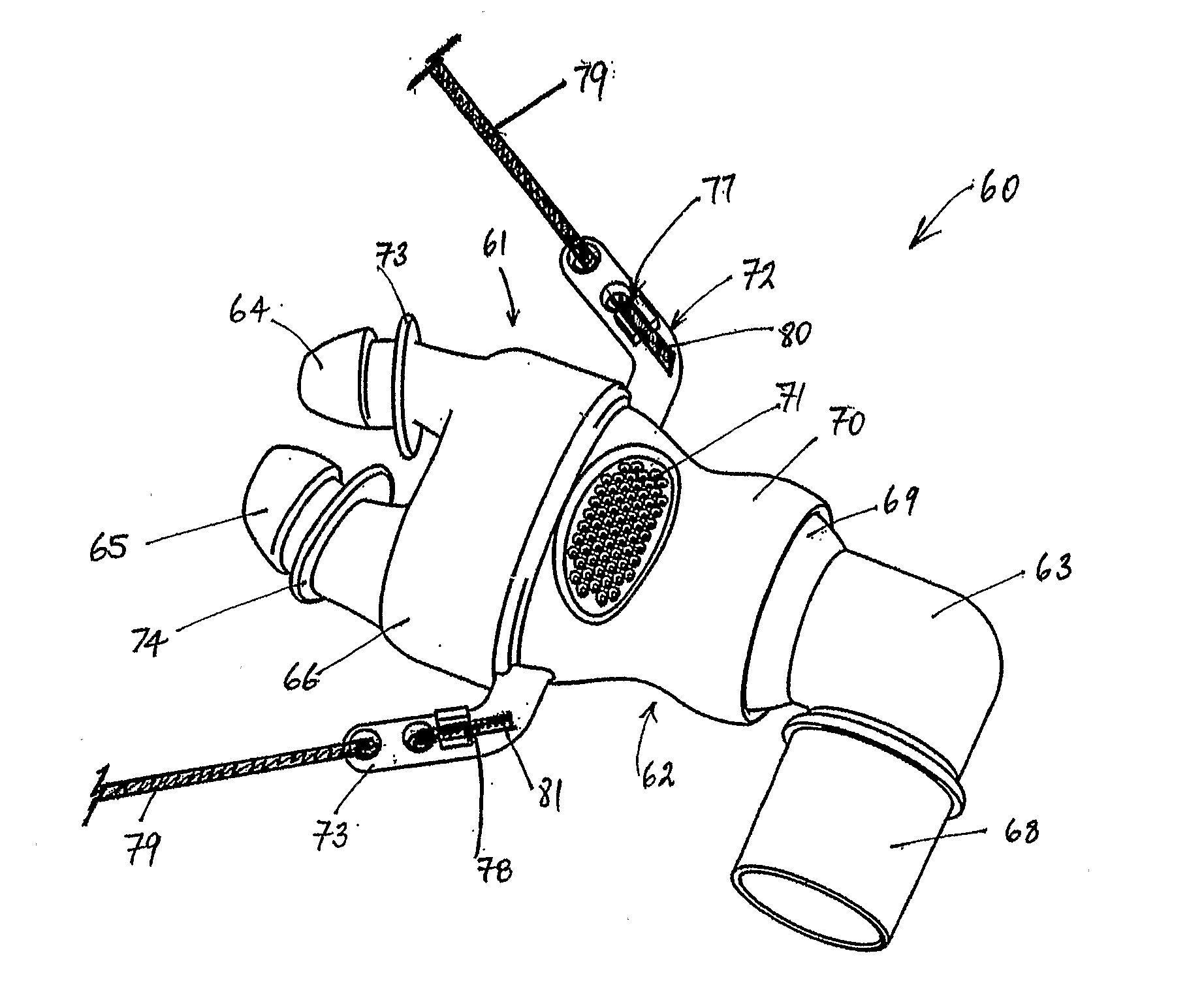
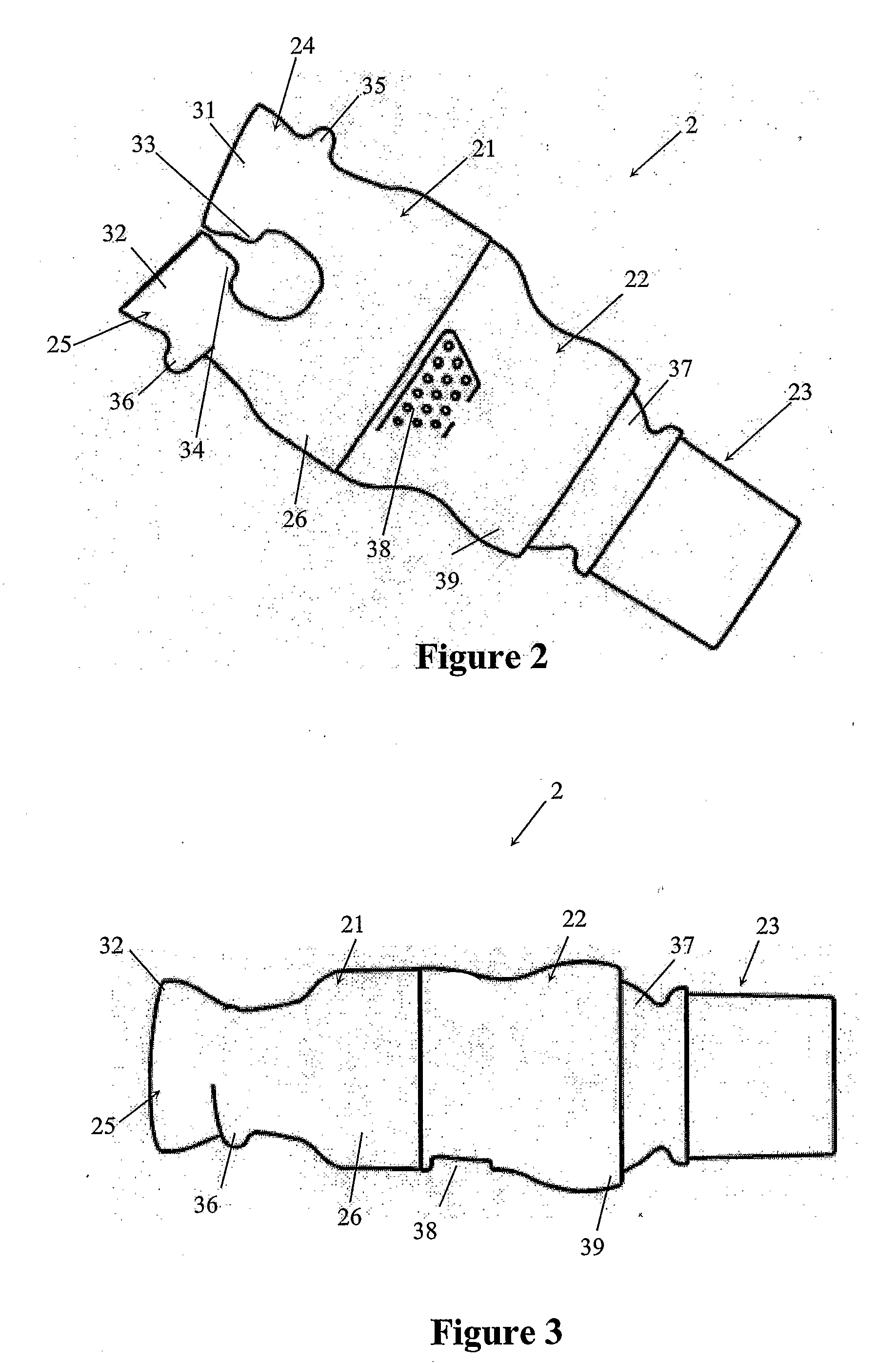
[0043]a nasal cannula of the present invention is shown in detail in FIGS. 2 to 6. Referring to FIGS. 2 and 6, the nasal cannula 2 comprises three main components; the prong part 21, body part 22 and ball connector 23.

[0044]The prong part 21 has two nasal prongs 24, 25, each of which are substantially shaped to follow the contours of the human nares and in use are placed inside a user's nares. The prongs 24, 25 extend out from a hollow tubular body 26 that in use fits to the body part 22. Each of the prongs 24, 25 are integrally moulded with the tubular body 26 in a flexible plastics material or rubber, such as silicone, other thermoset elastomers or thermoplastic elastomers such as Kraton™. The prongs 24, 25 are substantially oval tubular members that allow for a passage of gases. In particular, as shown in FIG. 5, the prongs are oval in shape and angled in the same manner as a human's nares. The prongs 24, 25 are angled toward one another (or toward the vertical axis Y) at the top...

second embodiment

[0053]the present invention is shown in FIG. 7. In this embodiment of the nasal cannula 42 the prongs 43, 44 are preferably small bore prongs for use with lower flow conditions. The prongs 43, 44 are similarly shaped to the prongs 24, 25 detailed above, but may not seal in the same manner as the abovementioned prongs due to the smaller size of the prongs. In fact these prongs may not seal at all in use within the user's nares.

[0054]Furthermore, in this second embodiment the nasal cannula 42 is smaller and weighs less as it is only comprised of a prong body 45 and prongs 43, 44, where the body 45 is connected to a small tube that is formed with corrugations or bellows 48 that connect to an inspiratory tube or conduit 47 (similar to the inspiratory conduit 3 described above) that receives a supply of gases.

[0055]The corrugations of bellows 48 will bend or move when a weight or force is placed on the cannula, thereby preventing dislodgement of the cannula 42 from a user's face in use. ...

third embodiment

[0058]the nasal cannula of the present invention is shown in FIG. 8 where the cannula may be provided with corrugated or baffled sections on the prongs. The nasal cannula 49 of this embodiment is similar to that of FIG. 2 but the prongs 50, 51 have a series of corrugations 52, 53 formed in them. The corrugations 52, 53 allow for movement of each of the prongs 50, 51 for a better user fit, and allow for movement of the cannula 49 without causing dislodgement of the prongs from the user's nares.

Angled Prong Nasal Cannula


PUM


Abstract

The present invention comprises a nasal cannula (2), shaped to fit within a user's nares, where the nasal cannula includes at least one prong (24, 25) allowing high flow delivery of humidified gases and creates positive airway pressure in the patient's airway. The prongs have angled ends (31, 32), such that in use, gases flowing through the prongs are directed to the user's nasal passages. The nasal cannula body is partially swivelling and preferably has a ball joint connector (37, 39). In another embodiment the nasal cannula may have at least one flared end prong (31, 32) that preferably seals within a patient's nare.

Description

FIELD OF INVENTION[0001]The present invention relates to apparatus for treating sleep apnoea. More specifically, the present invention provides a nasal positive airway pressure device.SUMMARY OF THE PRIOR ART[0002]Obstructive Sleep Apnoea (OSA) is a sleep disorder that affects up to at least 5% of the population in which muscles that normally hold the airway open relax and ultimately collapse, sealing the airway. The sleep pattern of an OSA sufferer is characterised by repeated sequences of snoring, breathing difficulty, lack of breathing, waking with a start and then returning to sleep. Often the sufferer is unaware of this pattern occurring. Sufferers of OSA usually experience daytime drowsiness and irritability due to a lack of good continuous sleep.[0003]In an effort to treat OSA sufferers, a technique known as Continuous Positive Airway Pressure (CPAP) was devised. A CPAP device consists of a gases supply (or blower) with a conduit connected to supply pressurised gases to a pat...

Claims


Application Information

Patent Timeline
IPC IPC(8): A62B7/02A61H31/00A61M16/00A61M16/06A61M16/08A61M16/10A61M16/16A62B7/00A62B18/00
CPCA61M16/0666A61M16/0683A61M16/16A61M16/0875A61M2205/0216A61M16/0069A61M16/109A61M16/0616A61M16/0816A61M16/0825A61M16/024A61M16/0057A61M16/08
Inventor MCAULEY, ALASTAIR EDWINPRENTICE, CRAIG ROBERTGLEESON, OLIVER
Owner FISHER & PAYKEL HEALTHCARE LTD
Why Eureka
Try Eureka