Nasal dilator

Inactive Publication Date: 2005-12-27
JORDAN JOHN
View PDF14 Cites 142 Cited by
  • Summary
  • Abstract
  • Description
  • Claims
  • Application Information

AI Technical Summary

Benefits of technology

[0010]Each of the dilators has a beveled edge on each inner side between the top and bottom flanges. This beveled edge will allow the device to conform to the general shape of the nose for additional comfort of the user. The beveled edge will insure a secure fit within the interior of the nose. Additionally, the beveled edge will allow or permit the device to remain in the nose during normal operation.
[0011]Plastic is probably a preferred material for construction due to its cost and durability. The entire device will be cast as a single unit with a mold. The flanges, which are on the top and bottom of the respective annular openings will be plastic and part of that same mold. The purpose of the flanges is to provide a surface area for the device to grip the inside surface of the nose without causing irritation or damage to the interior of the nose.
[0012]It is an object of this device to provide nasal dilation, which is comfortable. It is another object to make the device portable and re-usable.

Problems solved by technology

The current device allows permanent dilation and does not incorporate the use of a cannula.

Method used


Image

  • Nasal dilator
  • Nasal dilator
  • Nasal dilator

Examples


Embodiment Construction

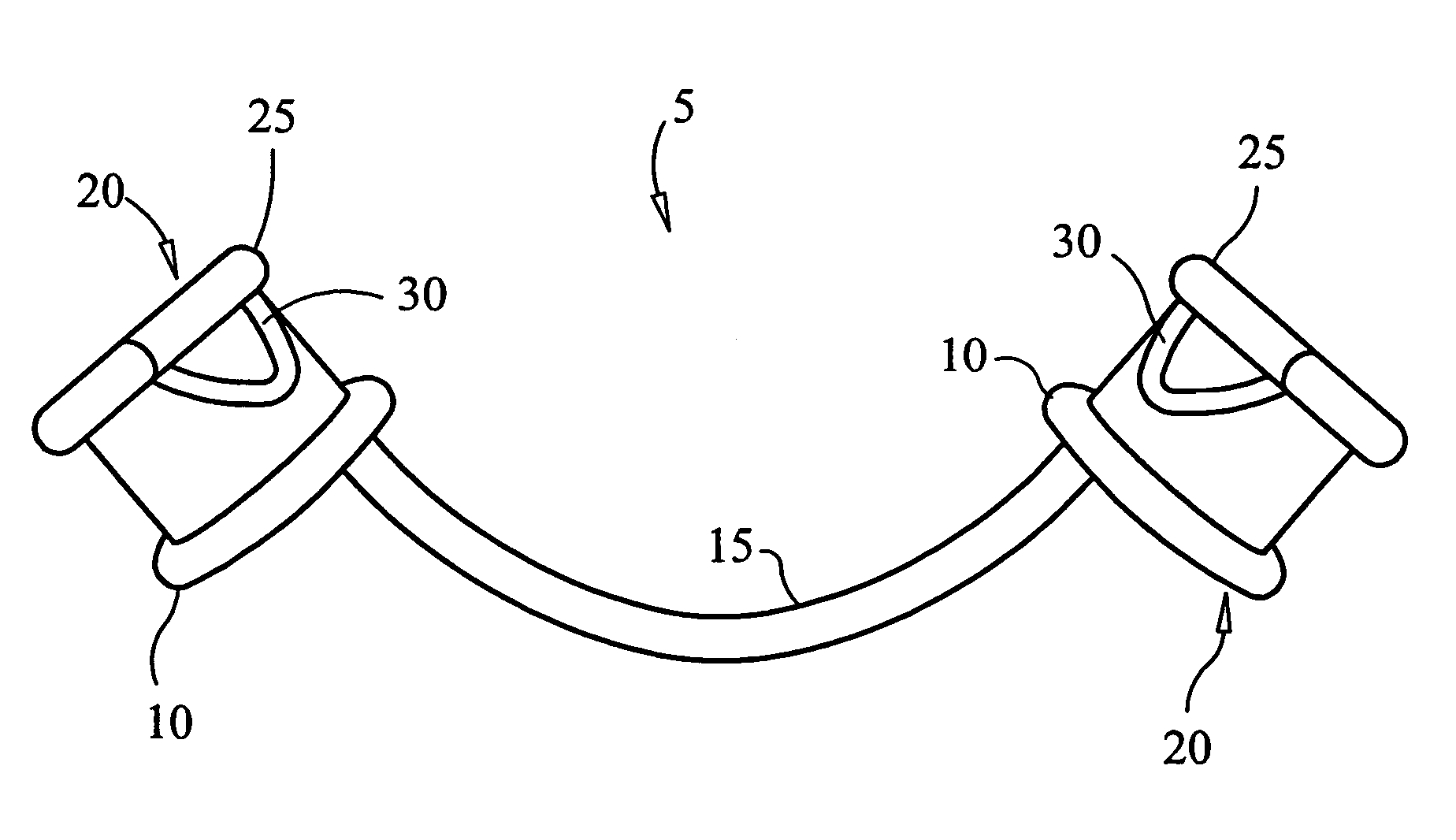
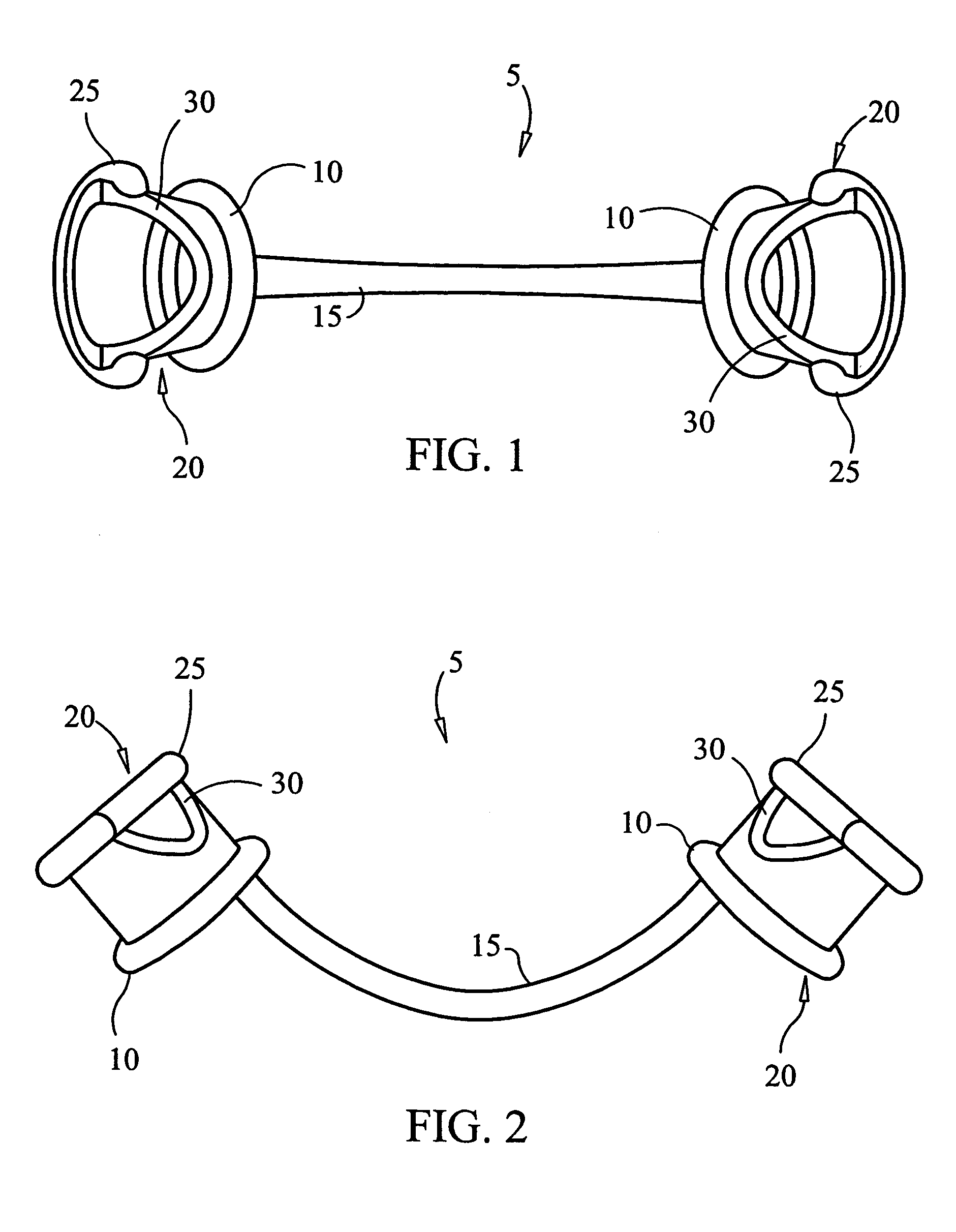
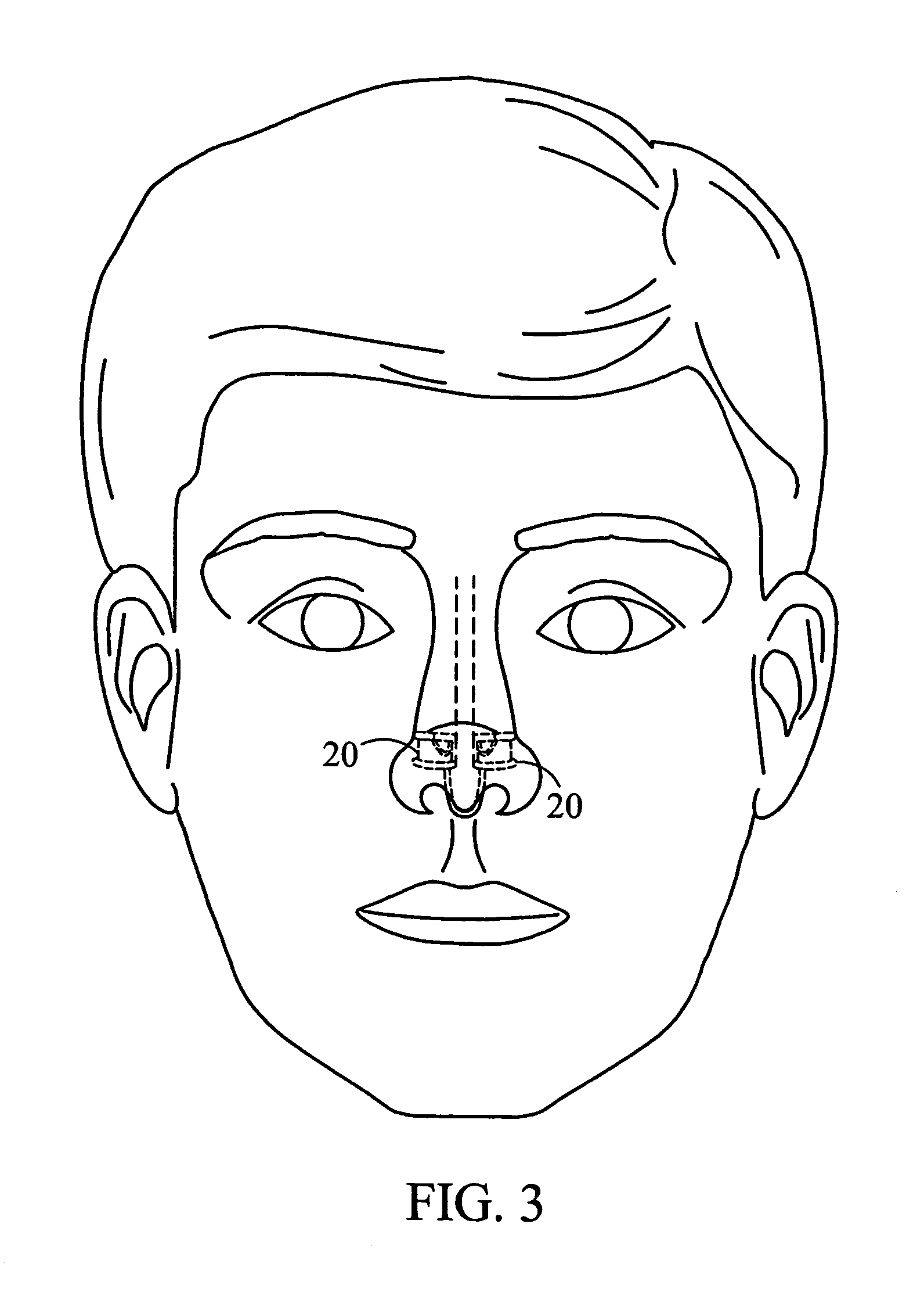
[0016]The device 5 is comprised of two separate nasal dilators 20 joined by a cord 15. FIG. 1, 2 The nasal dilators 20 are cylindrical and hollow and are designed to be inserted into a person's nasal cavities. FIG. 3.

[0017]A flange is provided on the top surface 25 and the bottom surface 10 of the nasal dilators. The flanges are installed to ensure a tight fit in the nose of the individual. The top flange 25 and bottom flange 10 are part of the molded device and are necessary to insure a secure fit within the nasal cavity.

[0018]Additionally, a beveled edge 30 is placed on the interior surface of the respective nasal dilators 20 between the top flange 25 and the bottom flange 10 surfaces. FIGS. 1, 2 The beveled edge 30 will extend from the top flange 25 to the approximate midpoint on the cylindrical surface between the top flange 25 and the bottom flange 10. FIGS. 1, 2 The beveled edge 30 allows the device 5 to better conform to the shape of the nose of an individual and allows a mor...


PUM


Abstract

This is a device which will provide nasal dilation and yet will provide comfort for the user. It will be portable and easily installed or removed by the user.

Description

CROSS REFERENCES TO RELATED APPLICATIONS[0001]Not ApplicableSTATEMENT REGARDING FEDERALLY SPONSORED RESEARCH[0002]Not ApplicableREFERENCE TO APPENDIX[0003]Not ApplicableBACKGROUND OF THE INVENTION[0004]A. Field of the Invention[0005]This relates to dilating the nasal cavities so that an individual can breathe with less difficulty. It is portable and will conform to the general shape of a nose. It does not use any auxiliary equipment and is not designed to be connected to a cannula.[0006]B. Prior Art[0007]There are many devices related to nasal dilation including those patents related to nasal dilation and cannulas specifically. Additionally, there are nasal dilators, which dilate internally and those that dilate externally. Examples of the prior art include Ellis U.S. Pat. No. 6,561,188, Strickland, U.S. Pat. No. 6,679,265 and Rittman, U.S. Pat. No. 6,270,512. Ellis and Strickland contemplate dilation with a cannula while the Rittman device contemplates a temporary dilation measure ...

Claims


Application Information

Patent Timeline
Patent Type & Authority Patents(United States)
IPC IPC(8): A61F5/08A61M15/08A61M16/00
CPCA61F5/08
Inventor JORDAN, JOHN
Owner JORDAN JOHN
Why Eureka
Try Eureka