Safety cabinet for antibiohazard
- Summary
- Abstract
- Description
- Claims
- Application Information
AI Technical Summary
Benefits of technology
Problems solved by technology
Method used
Image

Examples
Example
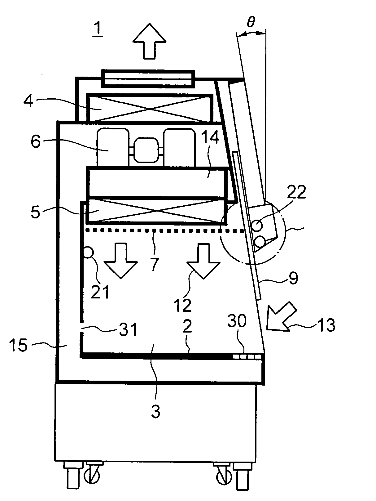
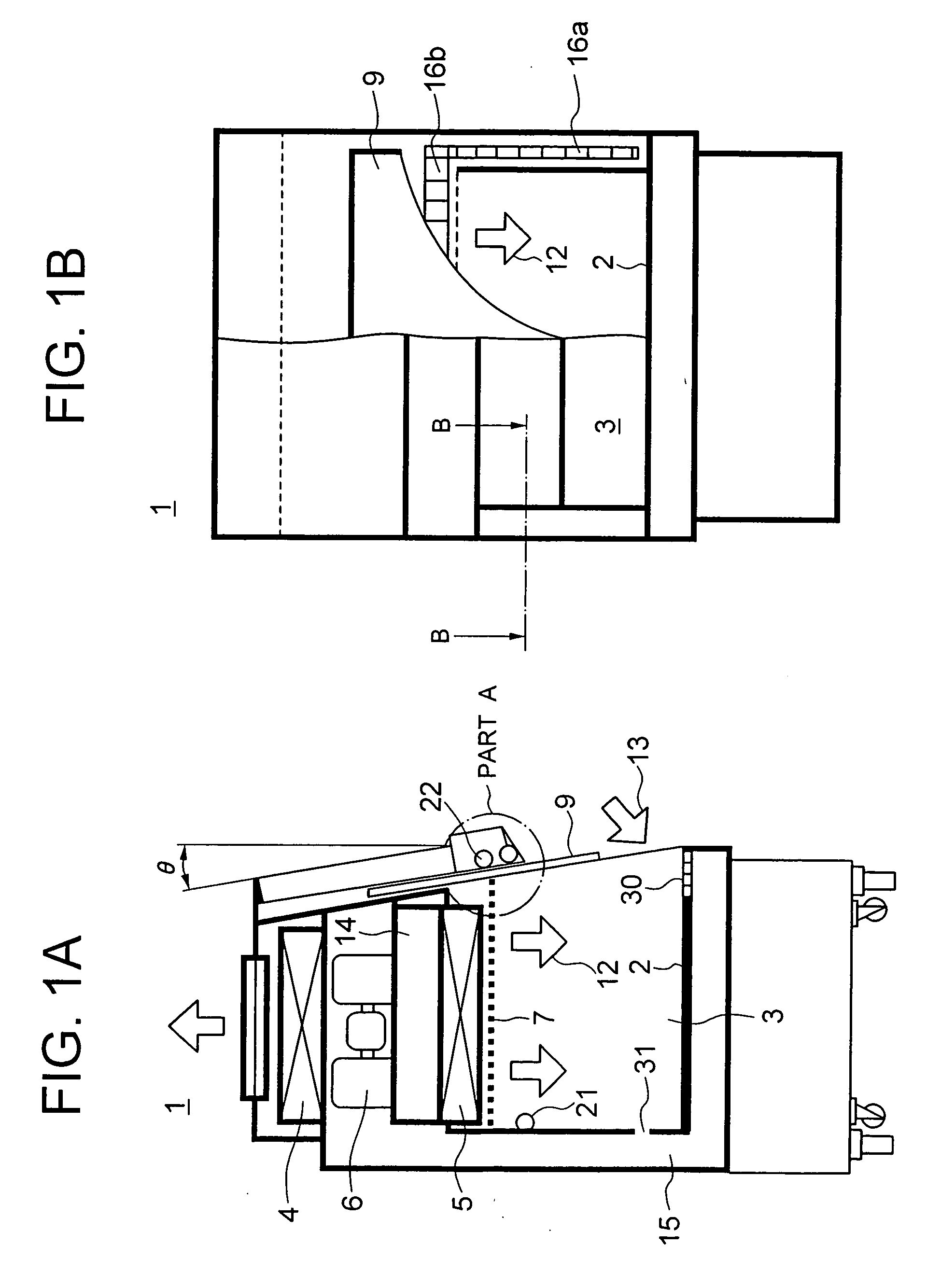
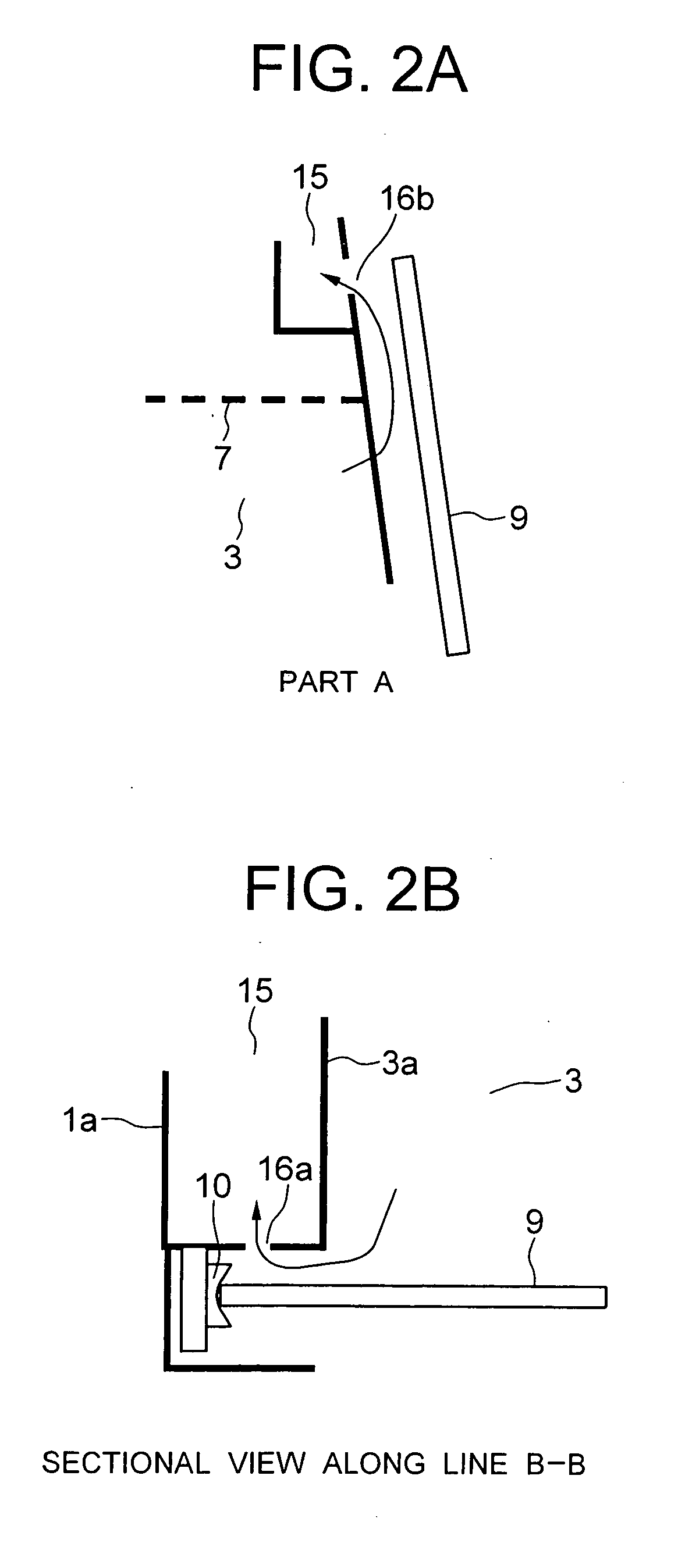
[0052]FIGS. 1a to 1b are views for explaining a first embodiment of the present invention. FIG. 1a is a vertical sectional view illustrating a safety cabinet, FIG. 1b is a front view illustrating the safety cabinet, FIG. 2a is an enlarged view illustrating a part in FIG. 1a, and FIG. 2b is a sectional view along line B-B in FIG. 1b.
[0053] In the first embodiment, air suction ports opposed to the inner surface of a front shutter are provided in the upper part and opposite side parts of a working space.
[0054] Referring to FIGS. 1a to 2b; there are shown a safety cabinet 1, a body casing 1a of the safety cabinet 1, a workbench 2, a working space 3, a side surface 3a of the working space 3, an exhaust air HEPA filter 4, an intake air HEPA filter 5, a blower 6 as a blowing means, blow-off rectifying vanes 7, a front shutter 9, air 12 blown into the working space 3, inflow air 13 from the outside of the safety container, a positive pressure contamination plenum 14, a negative pressure c...
Example
[0056]FIGS. 3a to 4b are views for explaining a second embodiment of the present invention. FIG. 3a is a vertical sectional view illustrating a safety cabinet, FIG. 3b is a front view illustrating the safety cabinet shown in FIG. 3a, FIG. 4a is an enlarged view illustrating a part A in FIG. 3a, and FIG. 4b is an sectional view along line B-B in FIG. 3b.
[0057] In the second embodiment, the air suction ports in a part opposed to the inner surface of the front shutter 9 are provided along the front shutter rails at the opposite sides of the working space, and a seal wiper is also provided.
[0058] Referring to FIGS. 3a to FIG. 4b, there are shown a seal wiper 8 for inhibiting entrance of the outside air and discharge of the inside air, and air suction ports 16 provided in parts which are opposed to the inner surface of the front shutter 9 and which are along the front shutter rails in opposite side parts of the working space 3. No suction ports corresponding to the suction port 16b in ...
Example
[0060]FIGS. 5a to 6 are views for explaining a third embodiment of the present invention. FIG. 5a is a vertical sectional view illustrating a safety cabinet, FIG. 5b is a front view illustrating the safety cabinet shown in FIG. 5a, and FIG. 6 is an enlarged view illustrating a part A in FIG. 5a.
[0061] Referring to FIGS. 5a to 6, there are shown a front shutter 9 which stands in a vertical direction, and air suction ports 16a formed in parts which are opposed to the inner surface of the front shutter 9 and which are along the front shutter rails at opposite side parts of the working space 3. No suction ports corresponding to the suction ports 16b are provided in the upper side part of the working space 3. The working of the air suction ports 16a is the same as that of the second embodiment. The constitution and the working of the other parts in the third embodiment are the same as those in the second embodiment.
[0062] With the configuration of the third embodiment, due to the sucti...
PUM
| Property | Measurement | Unit |
|---|---|---|
| Pressure | aaaaa | aaaaa |
| Angle | aaaaa | aaaaa |
Abstract
Description
Claims
Application Information
 - R&D Engineer
- R&D Manager
- IP Professional
- Industry Leading Data Capabilities
- Powerful AI technology
- Patent DNA Extraction
Browse by: Latest US Patents, China's latest patents, Technical Efficacy Thesaurus, Application Domain, Technology Topic.
© 2024 PatSnap. All rights reserved.Legal|Privacy policy|Modern Slavery Act Transparency Statement|Sitemap