
Multispout hydration system

a multi-spout, hydration system technology, applied in the direction of flexible container closure, liquid transfer device, flexible tubular container, etc., can solve the problems of not being flexible, being regarded as heavy, and solid insulated bottles or containers are generally viewed as not well suited for cyclists, hikers, and risking the cap and/or the drinking mechanism falling onto the ground or floor

Inactive Publication Date: 2005-03-24
BROWN DENNIS B +1
View PDF45 Cites 45 Cited by
  • Summary
  • Abstract
  • Description
  • Claims
  • Application Information

AI Technical Summary

Benefits of technology

Enables convenient, contamination-free insertion of solids and liquids while allowing for hands-free fluid extraction and pressure application, maintaining structural integrity and reducing the risk of contamination during outdoor activities.

Problems solved by technology

Solid insulated bottles or containers typically have some form of glass or glass-like container within a housing and as a result are not flexible and may be regarded as heavy.
Such solid insulated bottles or containers are generally viewed to not be well suited for use by cyclists, hikers, cross country skiers and others who are involved in similar outdoor activity and who are transporting fluids on their person directly or by attachment to some other structure being carried or moved by them.
As a result, the user exposes the drinking mechanism to contamination from nearby surfaces and also runs the risk of knocking the cap and / or the drinking mechanism onto the ground or floor.
Should the user be out of doors, the result may be extensive contamination.
Of course contamination means that a user should undertake to clean whatever is contaminated.
Since effective cleaning requires soap or a germicide of some type, it can be seen that cleaning can be quite inconvenient in many situations such as when one is camping.
For such items, it can be seen that the user must again remove the cap and any drinking mechanism and thereby run the risk of contamination particularly because drinking mechanisms are not suitable candidates for a cap string or line to hold the cap attached to the flask.
Thus the user must free up a hand when the time to do so may be inconvenient if not risky.

Method used


Image

  • Multispout hydration system
  • Multispout hydration system
  • Multispout hydration system

Examples


Embodiment Construction

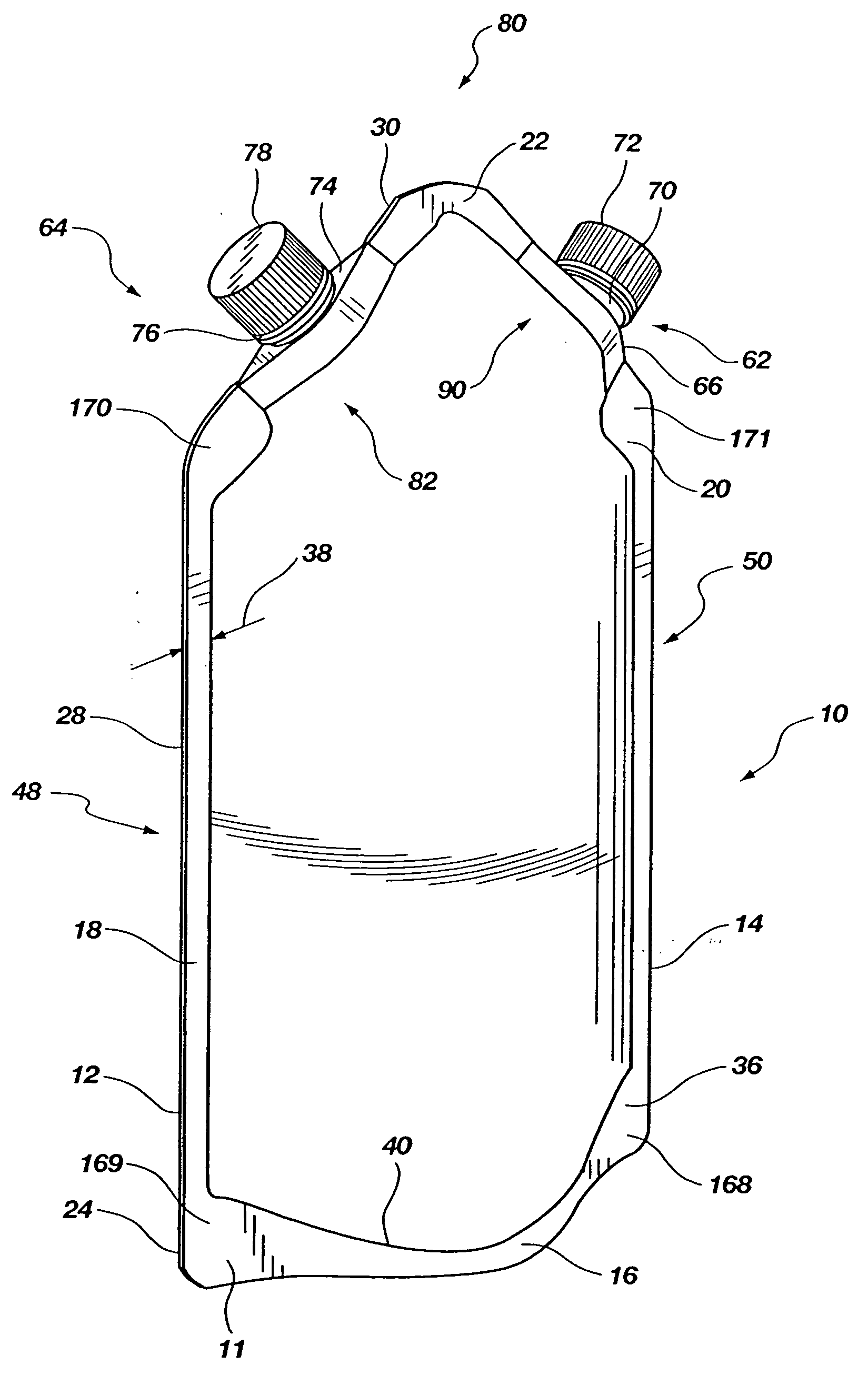
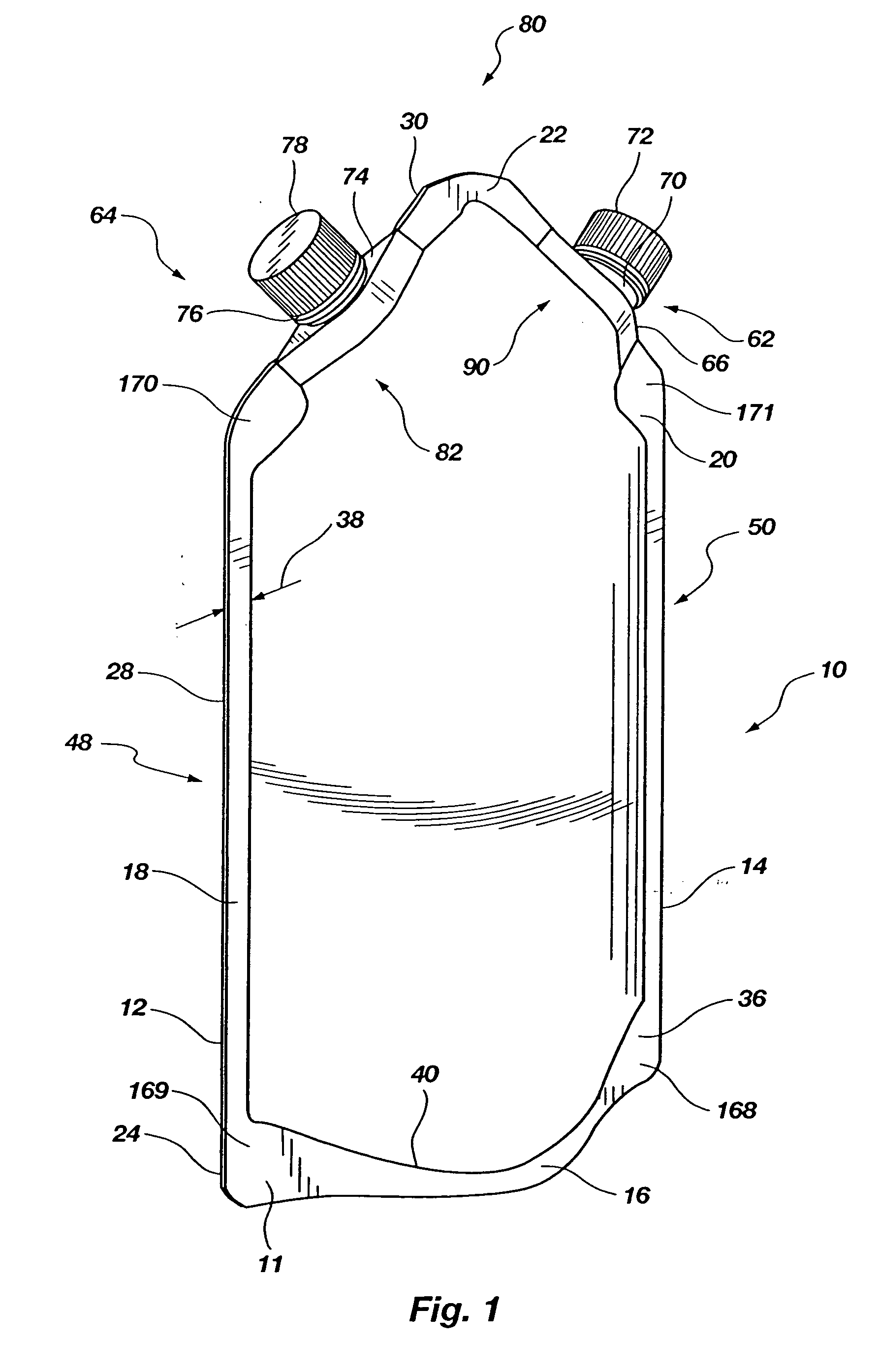
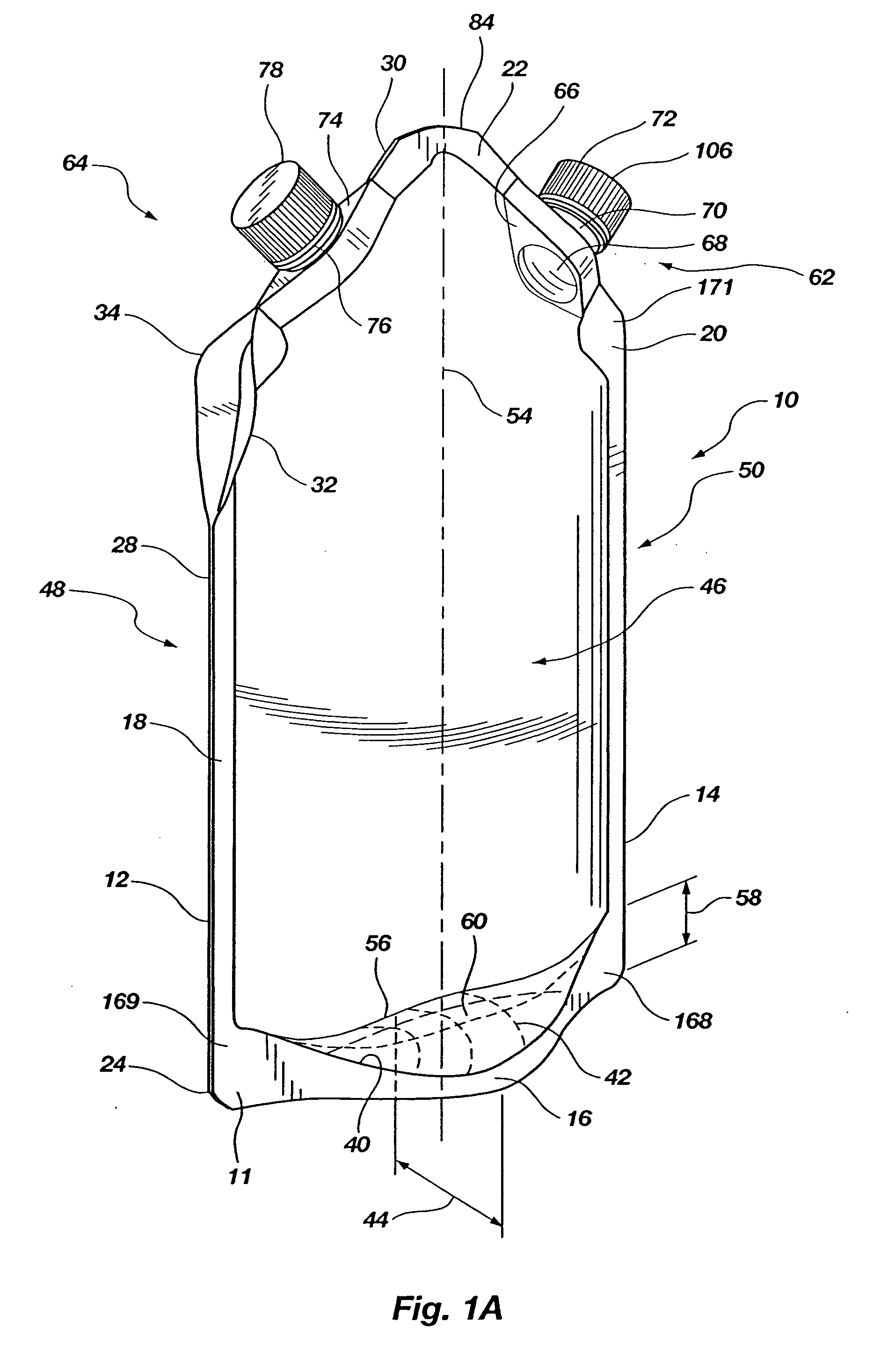
[0049] A flask 10 shown in FIGS. 1-5 has a first panel 11 and a second panel 12 of substantially identical shape joined to each other to form the flask 10 with flask perimeter 14. The first panel 11 has a bottom 16, a left side 18, a right side 20 and a top 22. Similarly, the second panel 12 has a bottom 24, a left side 26, a right side 28 and a top 30.

[0050] The first panel 11 and the second panel 12 are both made of pliable plastic and sized preferably identically. However, they may be different so that a user may trim excess or undesired material from one or the other panel so they end up about the same. Virtually any liquid or water retaining plastic will be suitable so long as it has sufficient strength to retain the liquids that are placed in the flask 10 and at the same time is essentially chemically inert to substances that may be placed in the flask 10 including, but not limited to, water, citrus drinks, fruit juices, food juices, alcoholic beverages, soups and the like. I...


PUM

PropertyMeasurementUnit
depthaaaaaaaaaa
distanceaaaaaaaaaa
angleaaaaaaaaaa

Abstract

A flask is formed of two panels heat sealed together along with a base or bottom insert. Two spouts are provided proximate the top one of which is for the extraction of fluids and the other of which is for the introduction of fluids. The flask may have a bite valve or a fluid conduit attached to one spout cap. Both spouts may be sealed into and along the edge of the flask. Alternately, one spout may be formed into a panel and the other into and along the edge of the flask. Alternately a pump may be provided to pump air into the flask to pressurize the fluid so that it will be urged out of the flask and through the bite valve when it is open.

Description

[0001] This application is a continuation in part of provisional application 60 / 178,802 filed Jan. 28, 2000.BACKGROUND [0002] 1. Field [0003] This invention relates to portable fluid carrying bottles or flasks used to carry liquids and more specifically to flexible bottles or flasks that are suitable for attachment to the person for carrying liquids including drinking liquids, beverages and soup-like foods and even more specifically to flexible flasks that have an associated pump for urging fluids therefrom. [0004] 2. State of the Art [0005] Many different styles and types of bottles or flasks are available to transport fluids and, more specifically, liquids such as water or some other similar liquid as well as foods like soups, beverages and the like. Solid insulated bottles or containers typically have some form of glass or glass-like container within a housing and as a result are not flexible and may be regarded as heavy. Such solid insulated bottles or containers are generally v...

Claims


Application Information

Patent Timeline
Patent Type & Authority Applications(United States)
IPC IPC(8): A45F3/16A45F3/20B65D30/16B65D33/38B65D75/58
CPCA45F3/20B65D11/04Y10S383/906B65D2575/583B65D75/5883
Inventor BROWN, DENNIS B.ROBERTSON, BREON J.
Owner BROWN DENNIS B
Learn More