
Voting ballot envelope

Active Publication Date: 2005-03-24
K & H PRINTERS LITHOGRAPHERS
View PDF18 Cites 30 Cited by
  • Summary
  • Abstract
  • Description
  • Claims
  • Application Information

AI Technical Summary

Benefits of technology

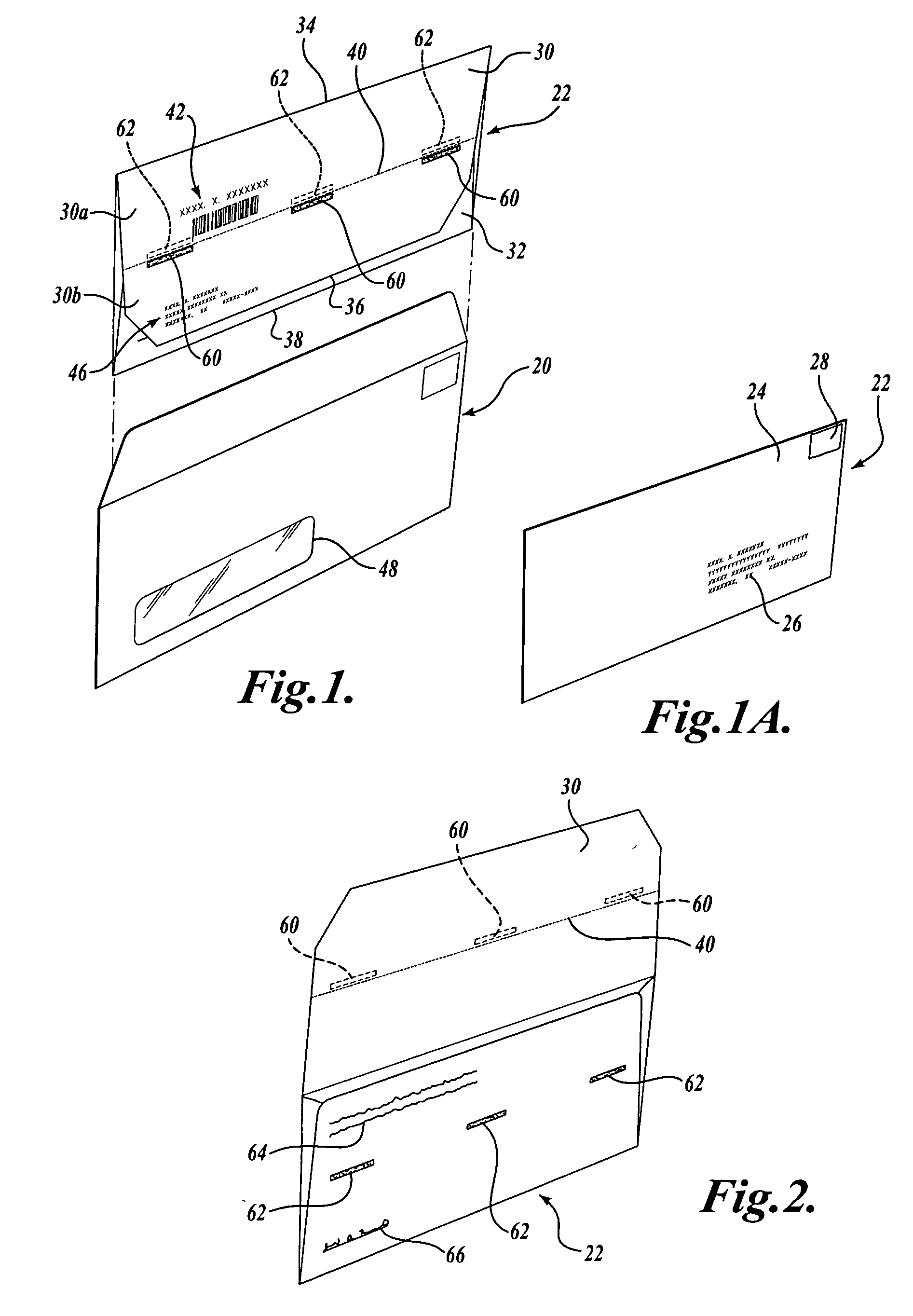
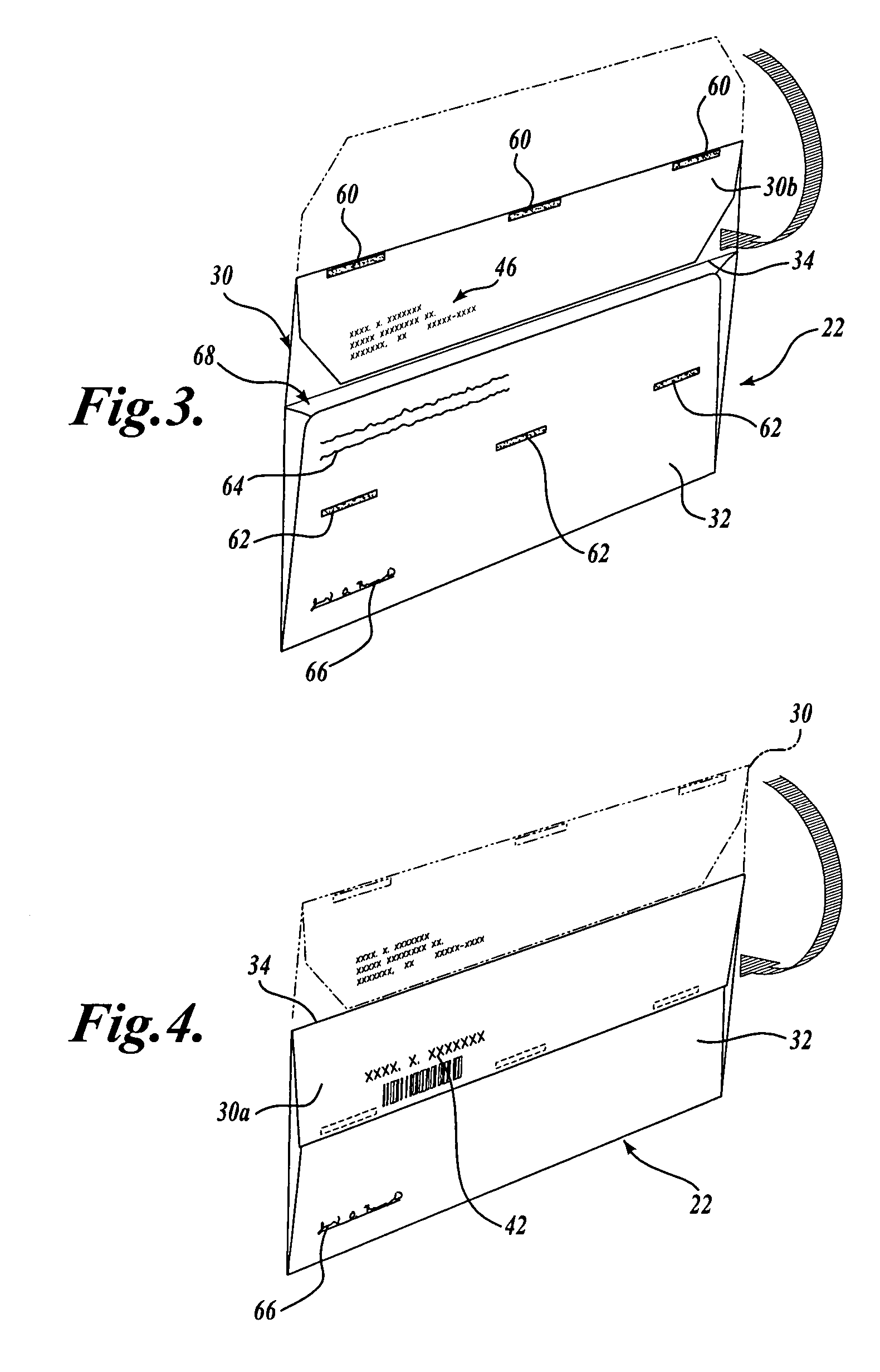
[0006] The present invention therefore provides a return envelope for a ballot on which the voter's address is printed, eliminates the possibility that the return envelope with an enclosed ballot will be returned to the voter's address, and assures that it will be returned to the organization or service provider conducting the election. In a preferred embodiment, the envelope has a front flap and rear flap joined to form a pocket at the upper end thereof. A third flap is joined to the upper edge of the front flap along a first zone of weakness. The third flap is foldable along the first zone of weakness in a rearward and downward direction to a first position located behind the rear flap. The third flap in the first position has an upper portion joined to the front flap along the first zone of weakness and a second portion joined to the first portion along a second zone of weakness. The first portion has first address information printed thereon and is visible when the third flap is in the first position. The first portion has identifying indicia thereon corresponding to the first address visible when the third flap is in the first position. The third flap is further foldable upwardly to a second position above the front flap. The lower portion is foldable rearwardly and downwardly when the third flap is in the second position to a third position behind the first portion. The first and second portions are then foldable downwardly and rearwardly from the third position to a fourth position behind the second flap to close the pocket. At least one of the second portion and the rear flap has an adhesive thereon for adhering the second portion to the rear flap to seal the envelope.

Problems solved by technology

Although the postal service regulations call for the envelope to be delivered to the address on the side with the postage, it is still possible through human error for the envelope to be mailed or returned to the voter's address on the reverse side of the envelope.
Many schemes have been attempted to eliminate this from happening, but it still occurs on occasion even though there is a notice on the reverse side of the return envelope that the mail service is not to deliver to the voter's address.
If, of course, the envelope is returned to the incorrect address, that ballot may be postmarked and / or delivered too late for the particular election.

Method used


Image

  • Voting ballot envelope
  • Voting ballot envelope
  • Voting ballot envelope

Examples


Embodiment Construction

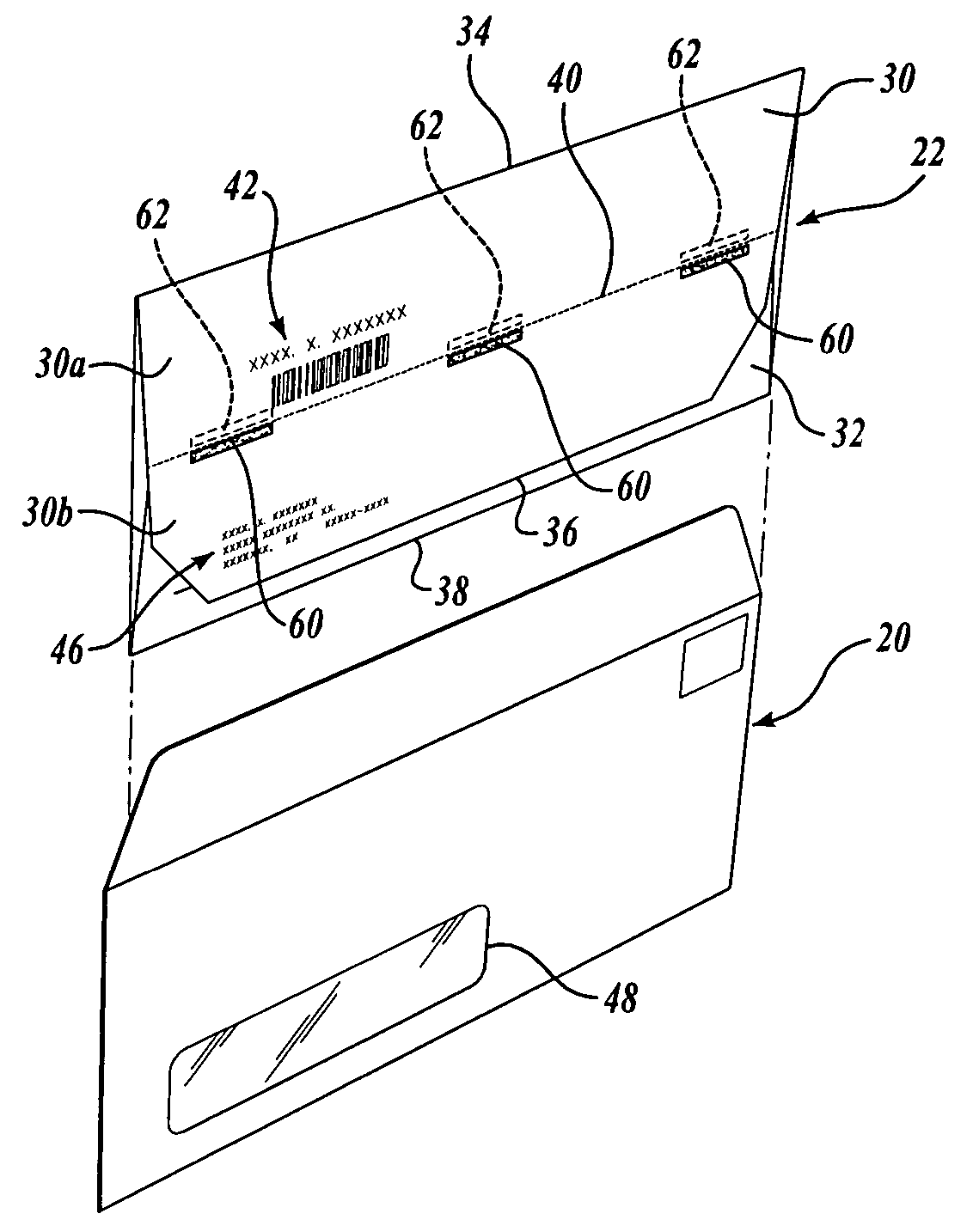
[0016] Referring to FIGS. 1 and 1A, an original mailing envelope 20 and a ballot return envelope 22 are shown positioned so that the return envelope 22 can be inserted in the original mailing envelope 20. When the voter receives the original envelope 20, it contains the return envelope 22 and an appropriate ballot (not shown). The front side 24 of the return envelope 22 contains the address 26 of the organization conducting the balloting to which the envelope 22 is to be returned. This organization could be a municipality, county, state, or an organization, such as a union or bar association. The front side 24 of the return envelope has a location 28 for affixing postage. Alternatively, a notice that the postage is prepaid can be printed on the envelope at this location 28.

[0017] The return envelope 22 carries a flap 30, which is shown folded downwardly toward the backside 32 of the return envelope 22. The flap 30 folds along a zone of weakness 34, in this embodiment a score line l...


PUM


Abstract

A return envelope for a ballot on which the voter's address is printed has a folding flap configured so as to eliminate the possibility that the return envelope with an enclosed ballot will be returned to the voter's address and assures that it will be returned to the organization of service providing or conducting the election. The envelope flap also is folded so as to provide verification information from the voter while maintaining the contents of the envelope secret.

Description

CROSS-REFERENCE TO RELATED APPLICATION [0001] This application claims the benefit of U.S. Provisional Application No. 60 / 497,033, filed Aug. 22, 2003. Priority under 35 U.S.C. § 119(e) is hereby claimed based on the provisional application.FIELD OF THE INVENTION [0002] This invention relates to preprinted return mailing envelopes, and more particularly, to envelopes used for returning mail-in or absentee ballots, which envelopes contain unique information identifying a particular voter. BACKGROUND OF THE INVENTION [0003] A significant number of ballots in various types of elections are cast via the mail. Ordinarily, the ballots and a return envelope are sent out in an original master envelope to the voter. The voter then marks the ballot, places it in the return envelope, and places the return envelope in the mail. The return envelope typically carries the address for the voter on the backside of the envelope. The original envelope has a see-through address window in it. The voter's...

Claims


Application Information

Patent Timeline
IPC IPC(8): B65D27/06G07C13/00
CPCG07C13/00B65D27/06
Inventor ACKLEY, JAY C.HAINES, DAVID W.HAINES, VERNON R.
Owner K & H PRINTERS LITHOGRAPHERS
Learn More