Differential pressure indicating device

Active Publication Date: 2021-10-07
HIRLEKAR GAURAV
View PDF0 Cites 0 Cited by
  • Summary
  • Abstract
  • Description
  • Claims
  • Application Information

AI Technical Summary

Benefits of technology

[0009]Another object of the present invention is to provide a coupling for a differential pressure indicator that eliminates the possibility of stalling phenomenon.
[0010]Still another object of the present invention is to provide a coupling to a differential pressure indicator that improves the robustness of the indicator to any vibrations it may be subjected to.
[0011]Still another object of

Problems solved by technology

While coming to the short comings of differential pressure gauges employing magnetic coupling, the 90° range of rotation of the follower magnet that moves the indicator is unsuitable for indicating a variety of differential pressure ranges on the same dial, especially when multiple scales of differing differential pressure ranges are to be shown on a single gauge.
Secondly, incorporating a driving magnet that travels out of the range of the follower magnet results in a wide variation in coupling strength between the magnets at various positions of the driving magnet.
Equally significantly, a reduction in magnetic coupling strength reduces the resistance of the follower magnet to vibration that the indicator may be subjected to, resulting in an oscillatory behavior of the indicating pointer, making the device difficult to read.
This is especially a problem when installed in mobile applications.
A final problem associated with a weak magnetic coupling is the tendency of the follower magnet to jump 180° on being driven by an impact force instead of the magnetic force of the driving magnet.
This makes the scale markings

Method used


Image

  • Differential pressure indicating device
  • Differential pressure indicating device
  • Differential pressure indicating device

Examples


Example

[0025]The foregoing objects of the invention are accomplished and the problems and shortcomings associated with prior art techniques and approaches are overcome by the present invention described in the present embodiments.

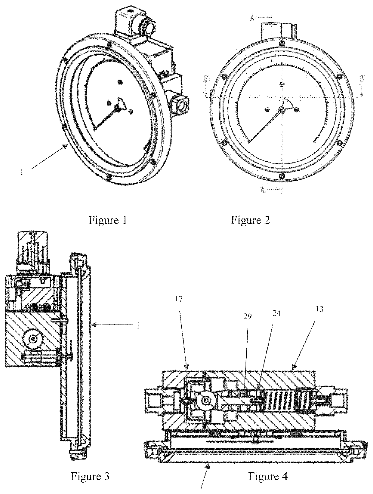
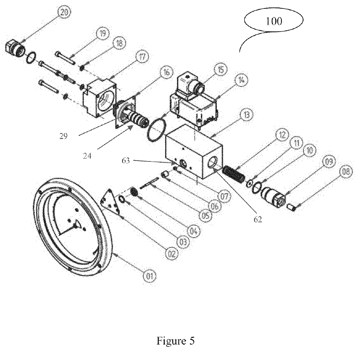
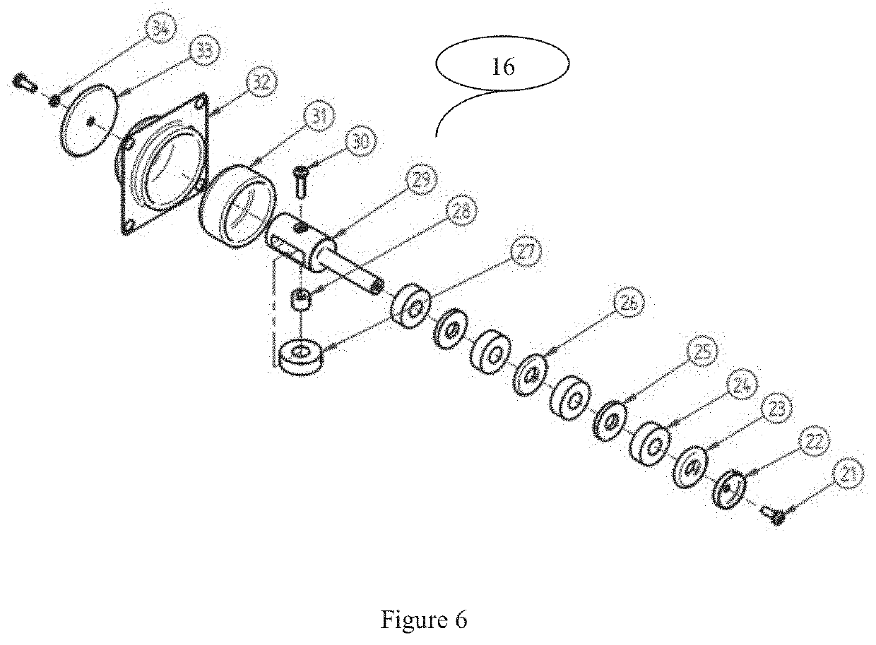
[0026]The present invention provides a differential pressure indicator with a magnetic coupling mechanism for having 90° to 270° angular range of the indicating member. The device comprises of a first split half and a second split half containing one half of a machined cavity and are sealed together with a rubber diaphragm between them and a piston pin assembly fitted in the cavity. A driving magnetic train having plurality of ring magnets with similar poles facing each other and separated by spacers is clamped on the piston pin. The rubber diaphragm receives differential pressure fluid on either of its surfaces and moves the piston pin assembly against a spring. A ring magnet magnetically coupled to the driving magnetic chain is pivotally fitted on the second spl...


PUM


Abstract

A differential pressure indicator includes a multi-polar driving magnets train clamped on a piston pin that moves in response to the changes in pressure conditions, thereby driving a multi-polar follower magnet carrying an indicating member, to move across a scale for a total angular range of 90° to 270°. The exact angular displacement of the follower magnet per unit linear displacement of the driving magnets train is decided by varying the relative magnetic strengths of the driving and follower magnets or by varying the spacing between adjacent magnets of the driving magnetic train. Further, magnetic flux of an auxiliary magnet fitted on the piston pin at a 90° orientation relative to the driving magnet train is utilized for actuating a magnetic switch in the switch assembly.

Description

CROSS-REFERENCE TO RELATED APPLICATION(S)[0001]This is a United States National Stage Patent Application that relies for and claims priority to International Patent Application No. PCT / IN2018 / 050471, filed on Jul. 20, 2018, and Indian Patent Application No. 201821010348, filed on Mar. 21, 2018, the entire contents of both of which are incorporated herein by reference.FIELD OF THE INVENTION[0002]The present invention relates to a differential pressure indicating device and more particularly it relates to a multi polar magnetic coupling mechanism of a differential pressure indicator having 270° angular range of an indicating pointer.BACKGROUND OF THE INVENTION[0003]Normally the differential pressure indicator is a device intended to measure differential pressures for gas, liquids such as water, or other chemical substances, etc., that is, differences in pressure for instance between two fluid lines that are intended to be connected to opposite ports of the indicator. U.S. Pat. No. 3,4...

Claims


Application Information

Patent Timeline
IPC IPC(8): G01L13/02G01D5/06
CPCG01L13/025G01D5/06G01L13/06G01L7/10G01L13/02G01L19/16
Inventor HIRLEKAR, GAURAV
Owner HIRLEKAR GAURAV
Why Eureka
Try Eureka