Straw Assembly for Compressed Air
- Summary
- Abstract
- Description
- Claims
- Application Information
AI Technical Summary
Benefits of technology
Problems solved by technology
Method used
Image
Examples
first embodiment
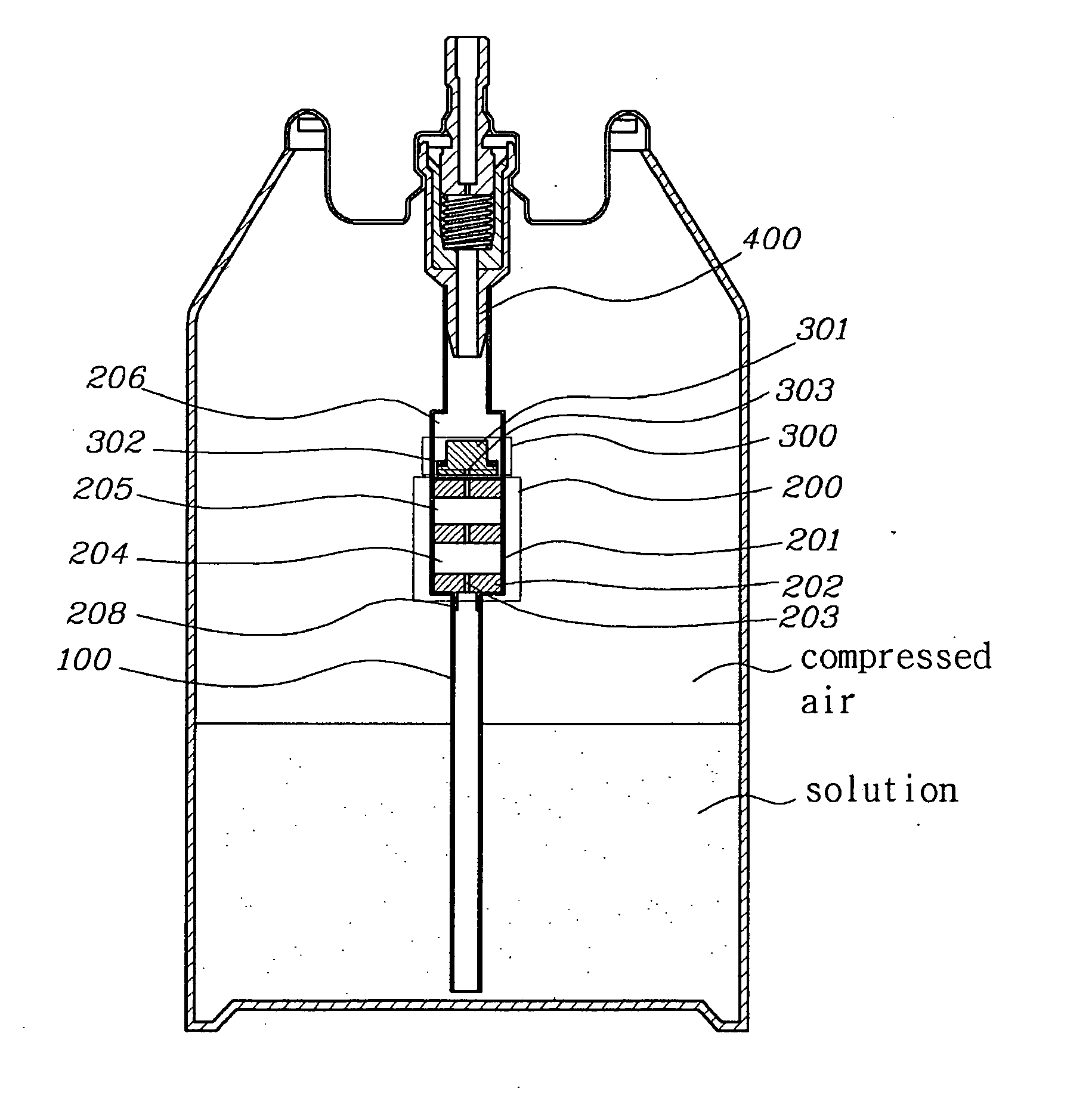
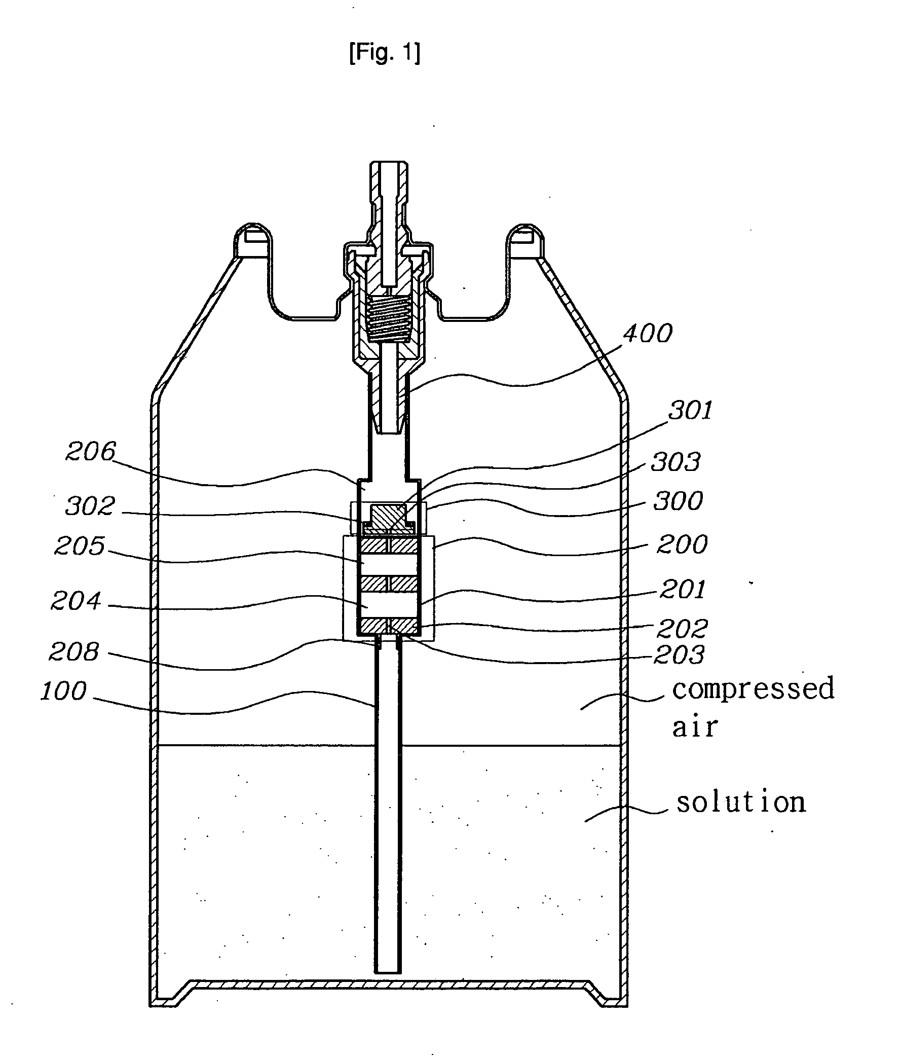
[0036]The present invention relates to a straw assembly for use in aerosol or spray injection type packing pressure containers configured to contain solution and compressed air therein. More particularly, as shown in FIG. 1, the straw assembly according to a preferred first embodiment of the present invention, which is installed in a pressure container, comprises: a valve unit 400 installed at an outlet of the container; a safety valve 300 that is located below the valve unit 400 and adapted to prevent discharge of compressed air serving as an injection propellant when the container is inverted; a pressure regulator 200 that is located below the safety valve 300 and adapted to sequentially regulate a pressure of the solution to a desired injection pressure; and a solution straw 100 coupled to a lower end of the pressure regulator 200 to be installed on an extension axis of the pressure regulator 200.
second embodiment
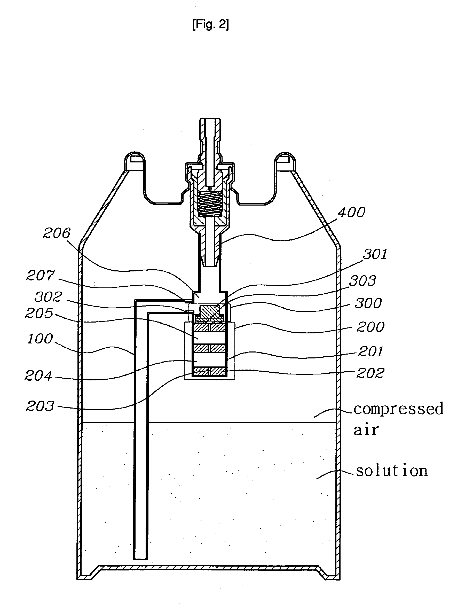
[0037]Alternatively, as shown in FIG. 2 illustrating a preferred second embodiment of the present invention, the solution straw 100 may be coupled to a circumferential position of the pressure regulator 200 at a side of the safety valve 300, and more particularly, may be coupled to an upper coupling portion 207 of the pressure regulator 200. Although not shown, also, it will be understood that the solution straw 100 may be directly connected to the valve unit 400 of the pressure container. In this configuration, the safety valve 300 and pressure regulator 200 may be installed below the solution straw 100.
third embodiment
[0038]Alternatively, as shown in FIG. 3 illustrating a preferred third embodiment of the present invention, the straw assembly of the present embodiment may comprise a vinyl bag device for preventing the leakage of compressed air and guaranteeing efficient injection of solution at all postures of the container, instead of the above described safety valve 300. The vinyl bag device includes a vinyl bag 304 for the storage of solution, a stopper 307 strongly attached around the solution straw 100 by use of an adhesive or other fastening means to prevent excessive movement of the vinyl bag 304 when the pressure container is inverted or shaked, and a conical fixture 305 strongly attached to a lower end of the solution straw 100 by use of an adhesive or other fastening means to prevent the vinyl bag 304 from clinging to an entrance of the solution straw 100. As will be understood, it should be essentially assumed that the solution straw 100 is coupled to the lower end of the pressure regu...
PUM
 Abstract
Description
Claims
Application Information
 - R&D
- Intellectual Property
- Life Sciences
- Materials
- Tech Scout
- Unparalleled Data Quality
- Higher Quality Content
- 60% Fewer Hallucinations
Browse by: Latest US Patents, China's latest patents, Technical Efficacy Thesaurus, Application Domain, Technology Topic, Popular Technical Reports.
© 2025 PatSnap. All rights reserved.Legal|Privacy policy|Modern Slavery Act Transparency Statement|Sitemap|About US| Contact US: help@patsnap.com


