Terminal seat

a terminal seat and seat technology, applied in the field of terminal seats, can solve the problems of difficult to obtain additional terminal seats and space, and be rather bothersome, and achieve the effects of convenient use, space saving, and convenient mounting and fixing

Inactive Publication Date: 2005-03-24
DELTA ELECTRONICS INC
View PDF4 Cites 2 Cited by
  • Summary
  • Abstract
  • Description
  • Claims
  • Application Information

AI Technical Summary

Benefits of technology

[0006] The object of the invention is to provide a terminal seat that can be dynamically piled up to increase the terminal numbers in correspondence to the requirement of wiring, and the whole terminal seat can be easily mounted and fixed.
[0007] A terminal seat according to the invention comprises a first receiving portion, a second receiving portion and a joint portion formed between the two. The second receiving portion corresponds to the first receiving portion and has similar shapes. The joint portion formed between the first receiving portion and the second receiving portion has a smaller lateral cross-section and a smaller lengthwise cross-section than the first receiving portion and the second receiving portion so as to form an annular groove. A plurality of terminal seats can be assembled together by a fixing member. The fixing member crosses the annular groove and fastens the assembly of the plurality of terminal seats. Adjacent terminal seats can be tightly assembled and save space. In comparison with conventional terminal seats, the terminal seat of the invention is compact, flexible and easy to use.

Problems solved by technology

Since the space in a device for mounting the terminal seat is usually limited, when it is required to increase additional wire connections, additional terminal seats and space are difficult to be obtained.
Because conventional terminal seats are made with a fixed number of terminals and mounting holes and require a certain space, additional terminal seats requires rearrangement of mounting space in the device, which is rather bothersome.

Method used


Image

  • Terminal seat
  • Terminal seat
  • Terminal seat

Examples


Embodiment Construction

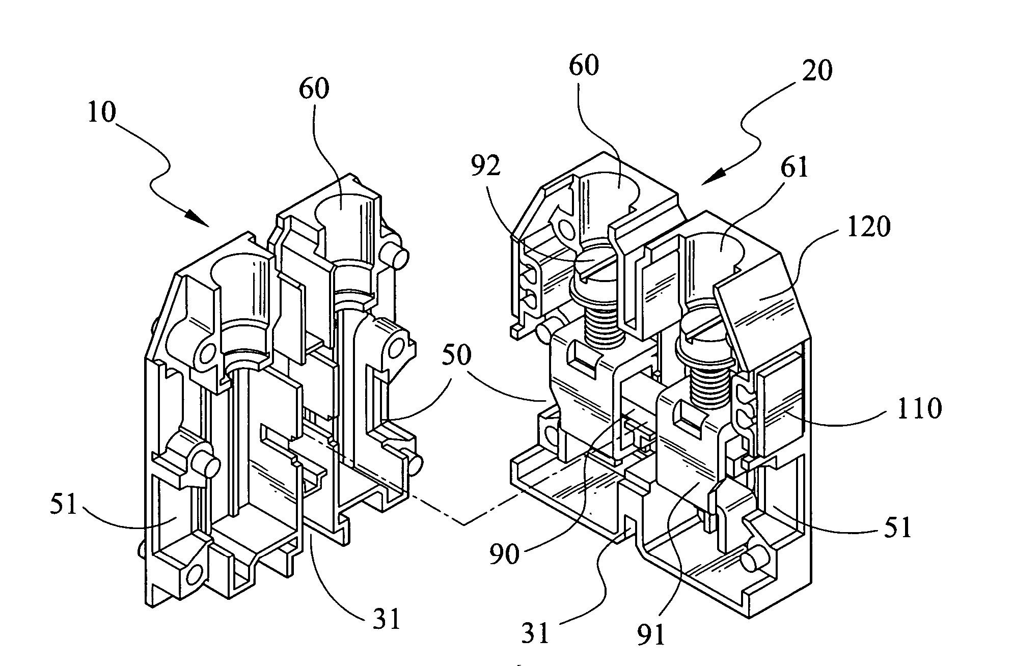
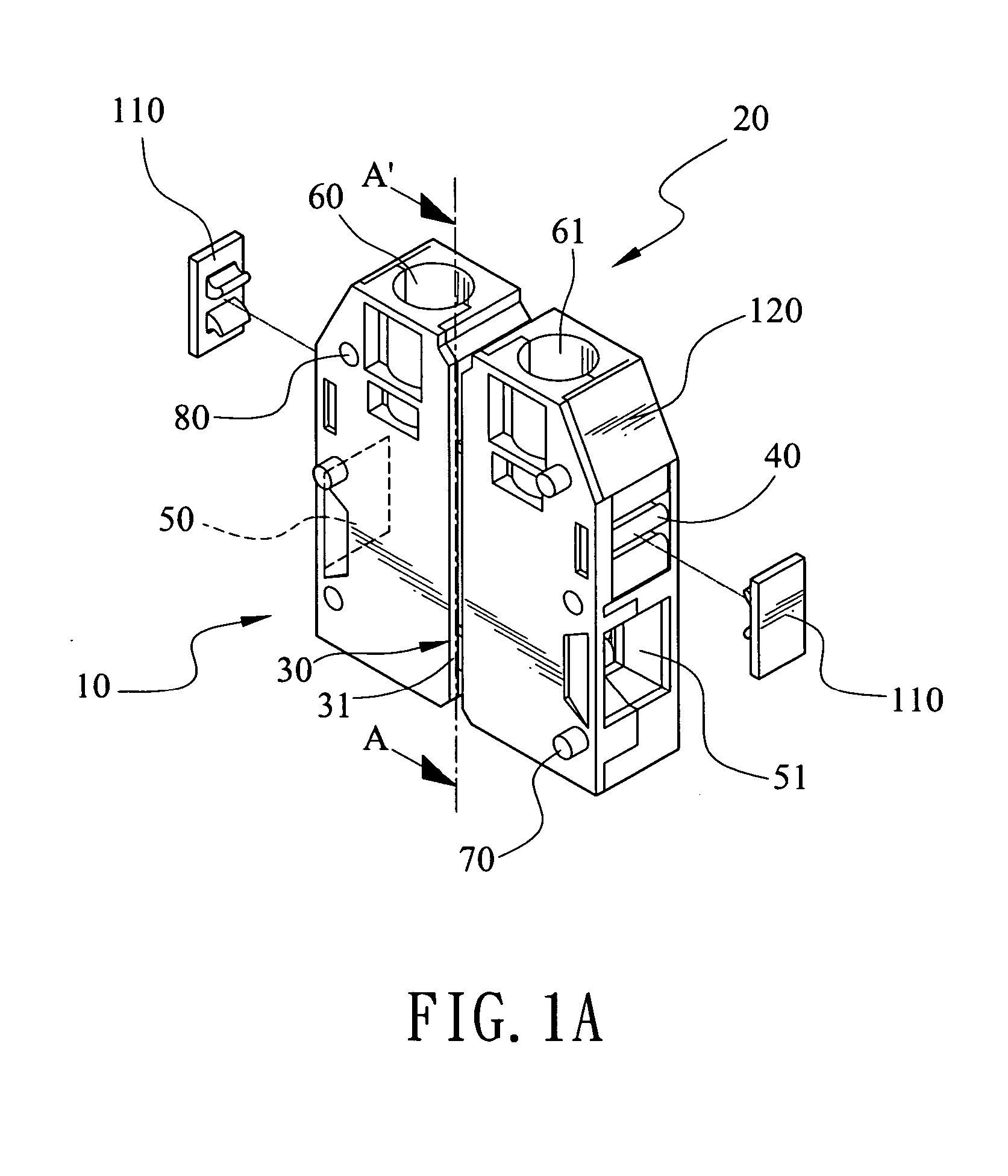
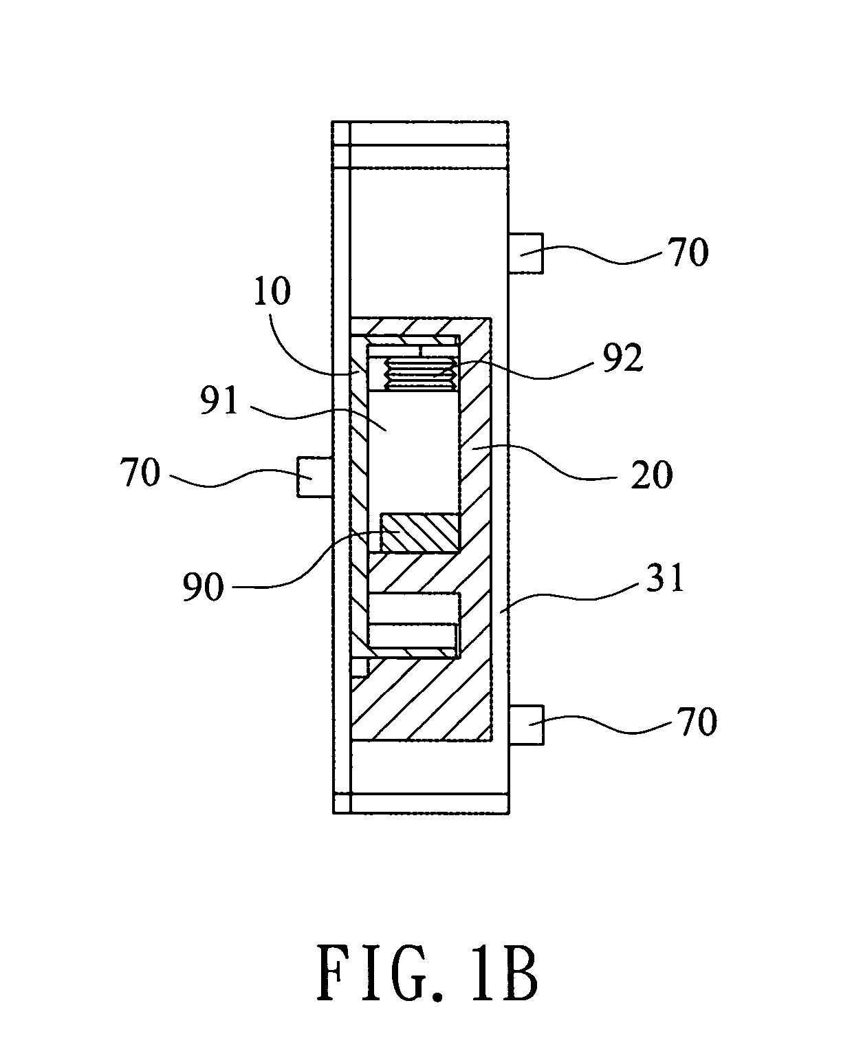
[0016] As shown in FIG. 1A and FIG. 1B, a terminal seat according to the invention comprises a first receiving portion 10, a second receiving portion 20 and a joint portion 30 formed between the two. The second receiving portion 20 corresponds to the first receiving portion 10 and has similar shapes. The joint portion 30 formed between the first receiving portion 10 and the second receiving portion 20 has a smaller lateral cross-section and a smaller lengthwise cross-section than the first receiving portion 10 and the second receiving portion 20 so as to form an annular groove 31, as shown in FIG. 11B, which is a sectional view taken along middle section A-A′ of FIG. 1A.

[0017] The first receiving portion 10 and the second receiving portion 20 are box-like members to be engaged with each other. The corners 120 can be used to have labels or prints (e.g. texts, numbers or icons) for identifications of wiring. There are also slots 40 formed on sides of the first and second receiving po...


PUM


Abstract

A terminal seat comprises a first receiving portion, a second receiving portion and a joint portion formed between the two. The second receiving portion corresponds to the first receiving portion and has similar shapes. The joint portion formed between the first receiving portion and the second receiving portion has a smaller lateral cross-section and a smaller lengthwise cross-section than the first receiving portion and the second receiving portion so as to form an annular groove. A plurality of terminal seats can be assembled together by a fixing member. The fixing member crosses the annular groove and fastens the assembly of the plurality of terminal seats.

Description

BACKGROUND OF THE INVENTION [0001] 1. Field of the Invention [0002] The invention generally relates to a terminal seat, and in particular relates to a terminal seat that is easy to be installed and easy to be made. [0003] 2. Related Art [0004] Recently, electromechanical industries are well developed. Many kinds of components are being improved. For instance, the terminal seats that connect external power sources to internal electric components have also been developed and used. [0005] The conventional terminal seats are used to be fixed by screws passing through some extrusions and holes formed on the seats. Since the space in a device for mounting the terminal seat is usually limited, when it is required to increase additional wire connections, additional terminal seats and space are difficult to be obtained. Because conventional terminal seats are made with a fixed number of terminals and mounting holes and require a certain space, additional terminal seats requires rearrangement...

Claims


Application Information

Patent Timeline
Patent Type & Authority Applications(United States)
IPC IPC(8): H01R4/36H01R9/18
CPCH01R4/363H01R12/7047H01R9/18
Inventor TSAI, CHIH-CHUNG
Owner DELTA ELECTRONICS INC
Why Eureka
Try Eureka