System for controlling a ventilation system

a ventilation system and control system technology, applied in the direction of ventilation control systems, space heating and heating equipment, heating types, etc., can solve the problems of difficult to adapt to older hvac systems, difficult and frequent problems such as the inability to control the temperature of individual rooms

Inactive Publication Date: 2005-04-21
HALABI KHALID
View PDF3 Cites 39 Cited by
  • Summary
  • Abstract
  • Description
  • Claims
  • Application Information

AI Technical Summary

Benefits of technology

[0012] It is a further object of the present invention to provide a room tem

Problems solved by technology

The problem of controlling the temperature of individual rooms has been a frequent issue in homes, buildings and office buildings.
Some of the prior art systems have used a temperature controller which incorporates expensive switching mechanisms or the like and complex zone area controls.
Some of

Method used


Image

  • System for controlling a ventilation system
  • System for controlling a ventilation system
  • System for controlling a ventilation system

Examples


Embodiment Construction

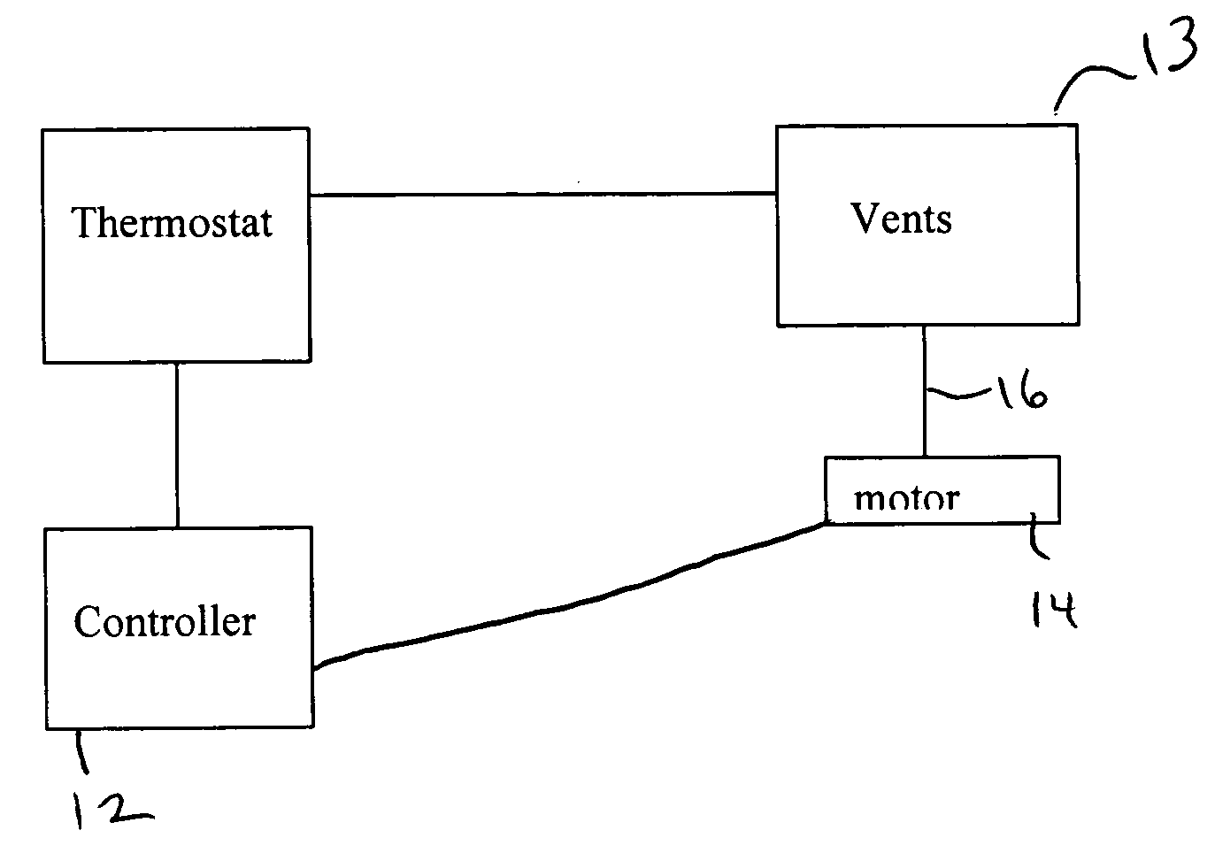
[0021] The present invention is described with reference to the enclosed Figures wherein the same numbers are utilized where applicable. The present invention is broadly directed to a system for controlling the temperature of a room or number of rooms, both for heating and / or air conditioning. The present invention is specifically directed to a system for controlling the temperature in a room. In particular, the present invention is directed to systems for controlling the temperature of specific rooms in a home or building.

[0022] The system in one embodiment may build upon existing technology and relies on the existing vents throughout the building. Vents in each room or area, open and close according to a pre-stored or pre-programmed profile for that room. The major objective of the invention is to match the desired set temperature for a particular area such as bedrooms at night while other areas can be set at a less costly temperature.

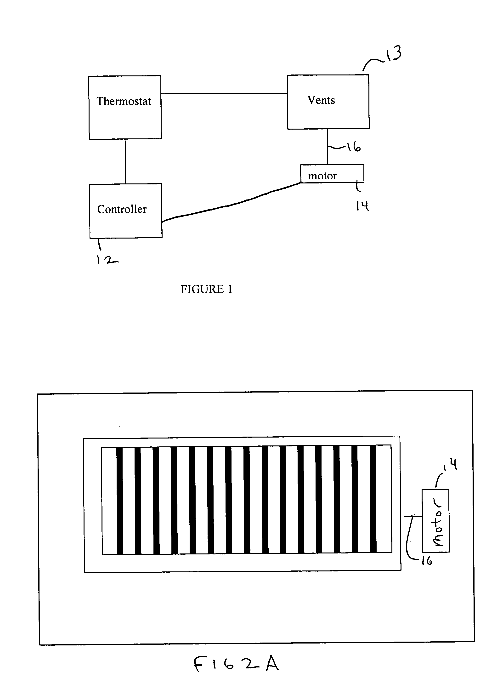
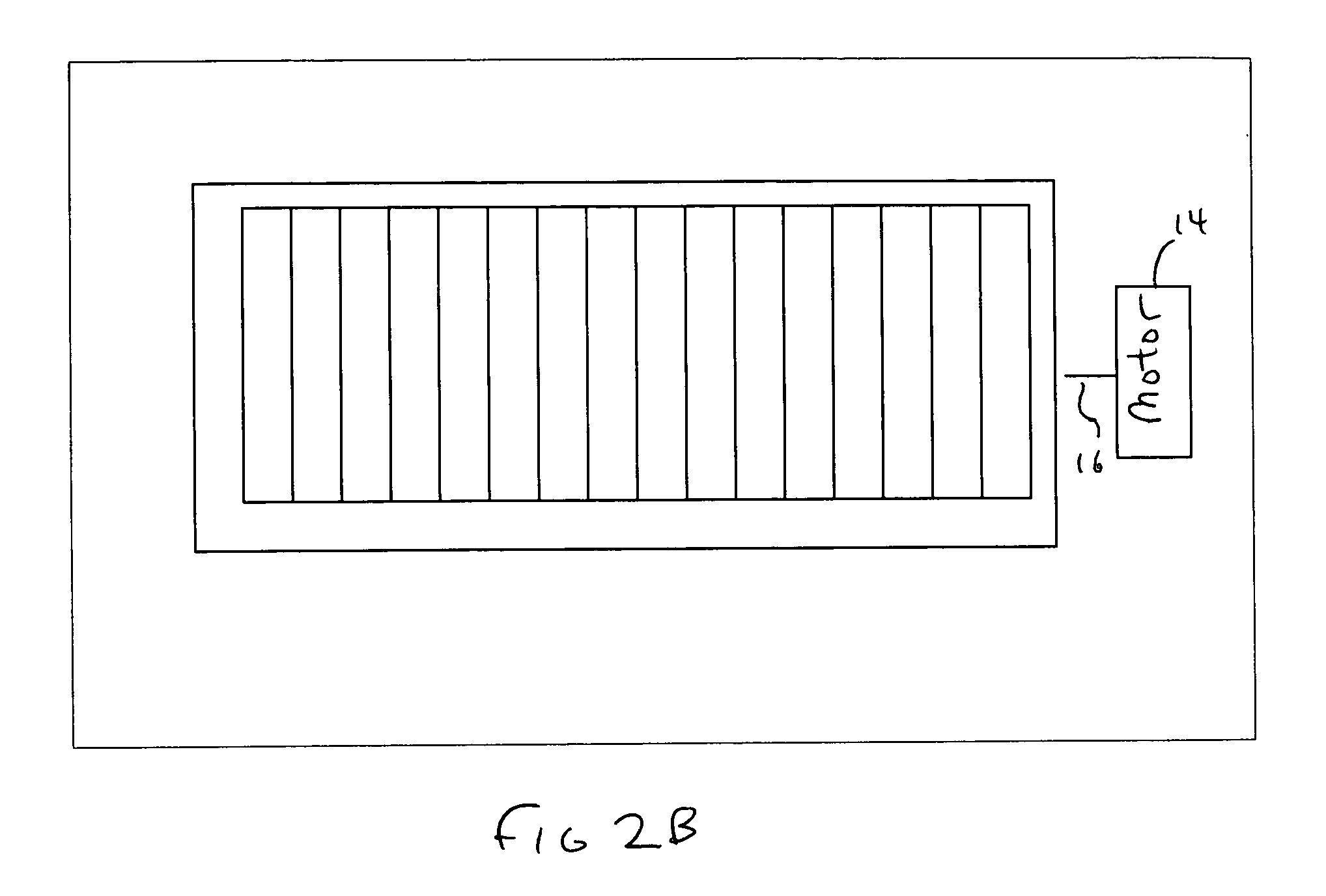
[0023] Referring to FIGS. 1, 2 and 3, the pr...


PUM


Abstract

A central system wherein conditioned or heated air is supplied to a plurality of rooms to be air-conditioned through a common duct, the system comprising: means for generating conditioned air or heated air and forcibly supplying the air to a plurality of rooms; a vent control mechanism, corresponding to a vent in each room, for controlling a flow of the conditioned air from the common duct into corresponding room; a room remote controller, provided in each room, including a command signal to control the operation of the vent control.

Description

FIELD OF THE INVENTION [0001] The present invention is directed to the field of temperature control for homes, buildings and offices. In particular, the present invention is directed to a system for controlling the temperature of the individual rooms and spaces within a building, office or home. BACKGROUND OF THE INVENTION [0002] The problem of controlling the temperature of individual rooms has been a frequent issue in homes, buildings and office buildings. Frequently, different locations of a home or office present different heating and cooling needs at different times of the day. For example, it is often desirable to cool the bedrooms of a house at night, while the temperature of the den or living room area may be of less significance. The increasing cost of energy coupled with the international situation has made it more important than ever to maximize energy conservation and efficiency. [0003] Heretofore, the problem of controlling individual room temperatures within a building...

Claims


Application Information

Patent Timeline
IPC IPC(8): F24F11/00F24F11/76
CPCF24F11/053F24F11/0012F24F11/30F24F2110/10F24F11/76F24F11/46F24F11/63F24F11/56F24F11/52
Inventor HALABI, KHALID
Owner HALABI KHALID
Why Eureka
Try Eureka