
Hybrid loop heat pipe

a heat pipe and loop technology, applied in the field of hybrid loop heat pipes, to achieve the effect of enhancing the flow of liquid, avoiding slowing down or opposition

Active Publication Date: 2005-04-28
THERMAL
View PDF21 Cites 7 Cited by
  • Summary
  • Abstract
  • Description
  • Claims
  • Application Information

AI Technical Summary

Benefits of technology

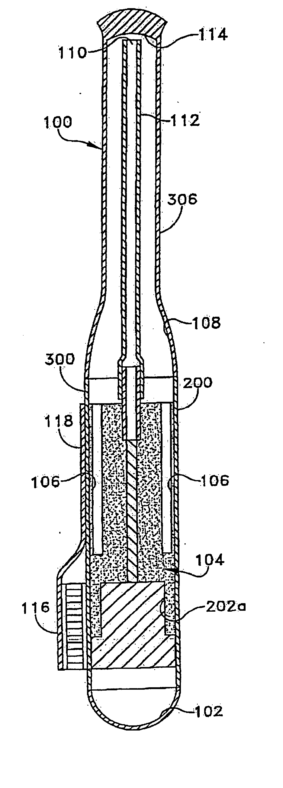
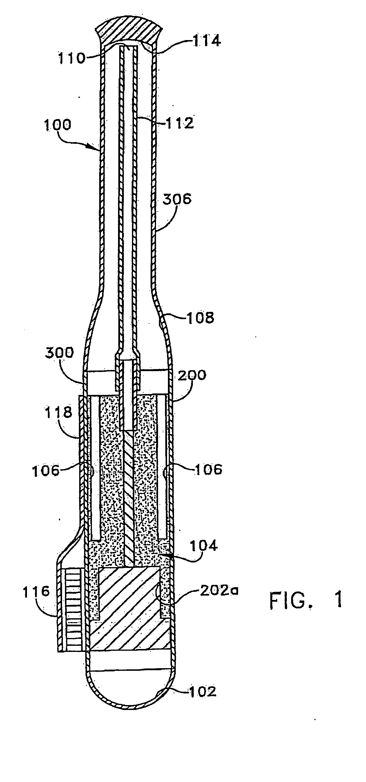
[0003] A heat pipe assembly according to the invention combines a reservoir and an evaporator in the same casing. The vapor flow is desirably toward a condenser of the heat pipe. The liquid flow is enhanced by capillary activity. Thus, the invention avoids slow down, or opposition to, the flow loop of the heat pipe.

Problems solved by technology

Combining the evaporator and reservoir would face the difficulty of combining vapor and condensate in the same casing, which would tend to cause thermal interaction of vapor and liquid.
Further, a combined evaporator and reservoir in the same casing would contribute further parasitic heating of the reservoir due to the industry known, heat leak problem associated with a loop heat pipe.

Method used


Image

  • Hybrid loop heat pipe
  • Hybrid loop heat pipe
  • Hybrid loop heat pipe

Examples


Embodiment Construction

[0010] This description of the exemplary embodiments is intended to be read in connection with the accompanying drawings, which are to be considered part of the entire written description. In the description, relative terms such as “lower,”“upper,”“horizontal,”“vertical,”, “above,”“below,”“up,”“down,”“top” and “bottom” as well as derivative thereof (e.g., “horizontally,”“downwardly,”“upwardly,” etc.) should be construed to refer to the orientation as then described or as shown in the drawing under discussion. These relative terms are for convenience of description and do not require that the apparatus be constructed or operated in a particular orientation. Terms concerning attachments, coupling and the like, such as “connected” and “interconnected,” refer to a relationship wherein structures are secured or attached to one another either directly or indirectly through intervening structures, as well as both movable or rigid attachments or relationships, unless expressly described oth...


PUM

PropertyMeasurementUnit
thermalaaaaaaaaaa
heat transfer efficiencyaaaaaaaaaa
vapor pressureaaaaaaaaaa

Abstract

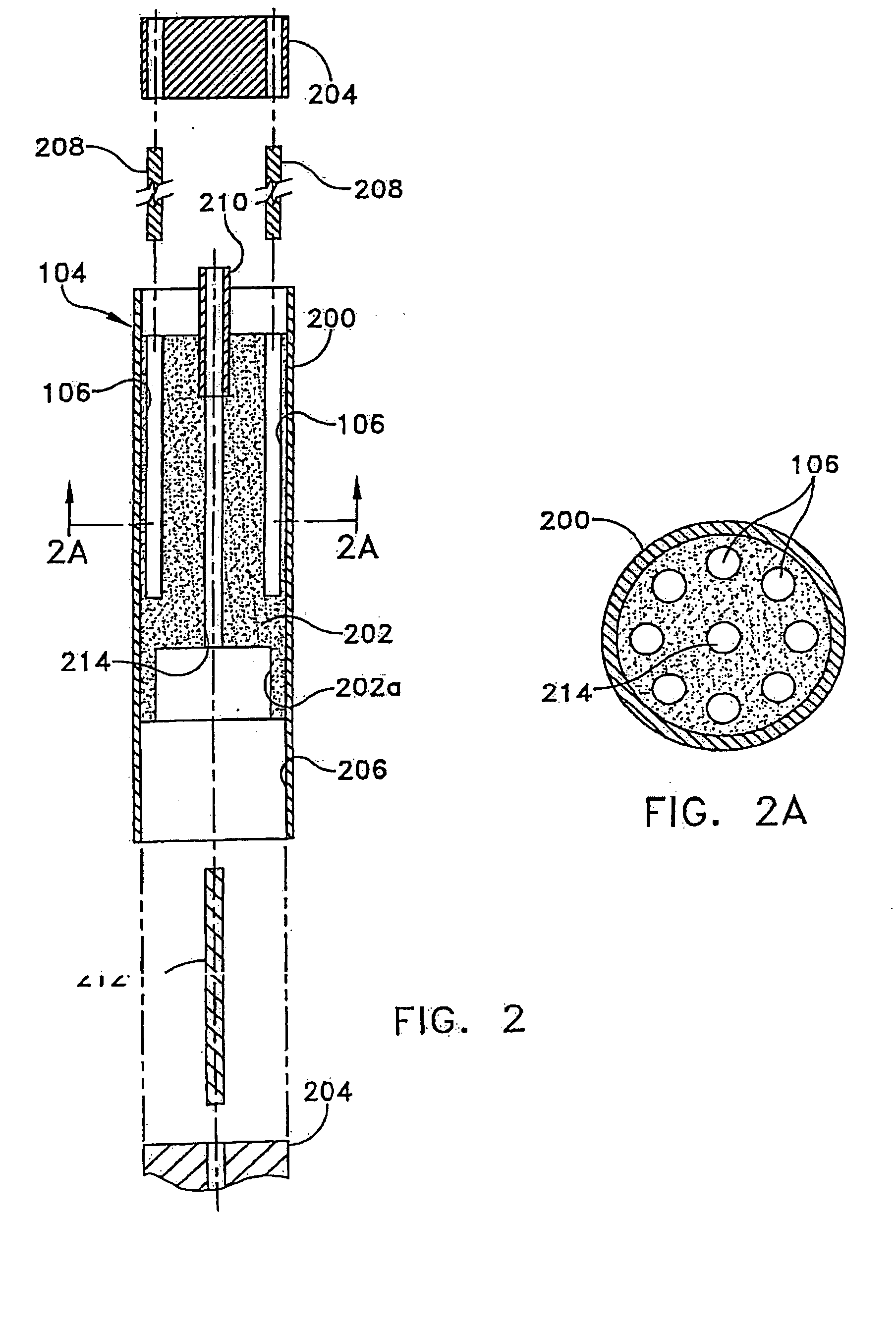
A heat pipe assembly (100) has a combined reservoir (102) and evaporator (104), the evaporator (104) having ducts of a vapor manifold (106) that exhausts vapor toward the condenser (108) instead of opposing the flow of liquid condensate to the reservoir (102), and the evaporator (104) having a wick passage that impels the condensate toward the reservoir (102) instead of opposing the flow of vapor.

Description

FIELD OF THE INVENTION [0001] The invention relates to the field of heat pipes, and more particularly relates to a hybrid heat pipe that combines a heat pipe with a supplementary cooling device. BACKGROUND [0002] U.S. Pat. No. 6,382,309 discloses a heat pipe assembly having an evaporator for vapor in a first casing, and a reservoir for condensate in a second casing. In addition to the space consumed by two casings, both casings are open one-to the-other and need to be hermetically sealed to support an evacuated internal environment. Combining the evaporator and reservoir would face the difficulty of combining vapor and condensate in the same casing, which would tend to cause thermal interaction of vapor and liquid. The heat transfer efficiency of the heat pipe would be reduced. Further, the flow loop of the heat pipe would be slowed by reduced vapor pressure and reduced liquid flow. Further, a combined evaporator and reservoir in the same casing would contribute further parasitic he...

Claims


Application Information

Patent Timeline
Patent Type & Authority Applications(United States)
IPC IPC(8): F28D15/02F28D15/04
CPCF28D15/0283F28D15/04Y10T29/49353Y10T29/49361F28D15/043F28D15/025F28F2270/00
Inventor WERT, KEVIN L.
Owner THERMAL
Learn More