
Ink jet ink set

a technology of black dyes and ink jets, applied in the field of black dyes, can solve the problems of low light fastness of this class of black dyes on a laminated receiving element, metal complex black dyes do not provide as neutral a tone, and the color of black dyes is not as bright as on

Inactive Publication Date: 2005-04-28
EASTMAN KODAK CO
View PDF16 Cites 36 Cited by
  • Summary
  • Abstract
  • Description
  • Claims
  • Application Information

AI Technical Summary

Benefits of technology

The patent text describes the ratio of two different metal complex black dyes in an ink composition. The ratio should be between 1 part of the first dye to 1-2 parts of the second dye, with a preferred ratio of 1:9 to 9:1. Additionally, the ratio of yellow dyes to the sum of the black dyes should be between 1 part yellow dye to 1-2 parts of the sum of the black dyes, with a preferred ratio of 1:9 to 1:5. This information helps to create a more precise and accurate ink composition for printing.

Problems solved by technology

The technical problem addressed in this patent text is to create a black ink for ink jet printing that can produce images with a neutral tone over a range of densities while providing high light fastness when printed on a variety of recording elements that are subsequently laminated. The text discusses various methods and colorants used in ink jet printing and the importance of light fastness and color gamut in creating high-quality images. The invention aims to address this problem by providing a new black ink that can achieve these goals.

Method used


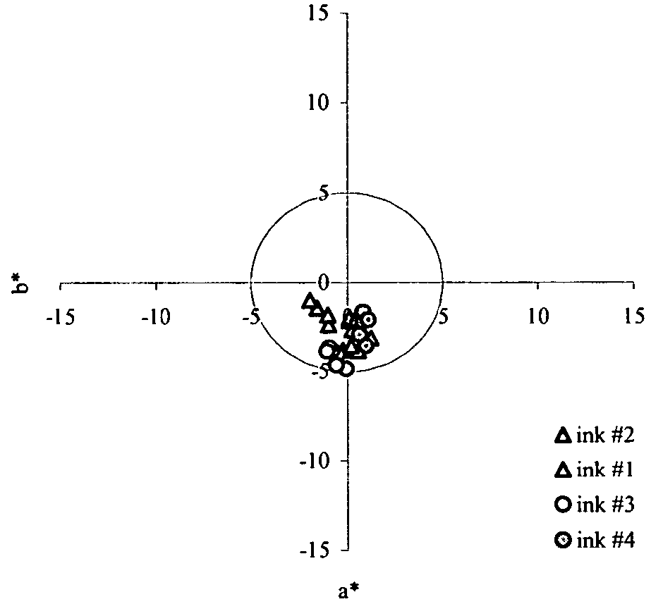
Image

  • Ink jet ink set
  • Ink jet ink set
  • Ink jet ink set

Examples


examples

Preparation of Inks

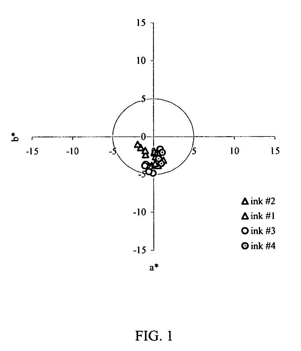
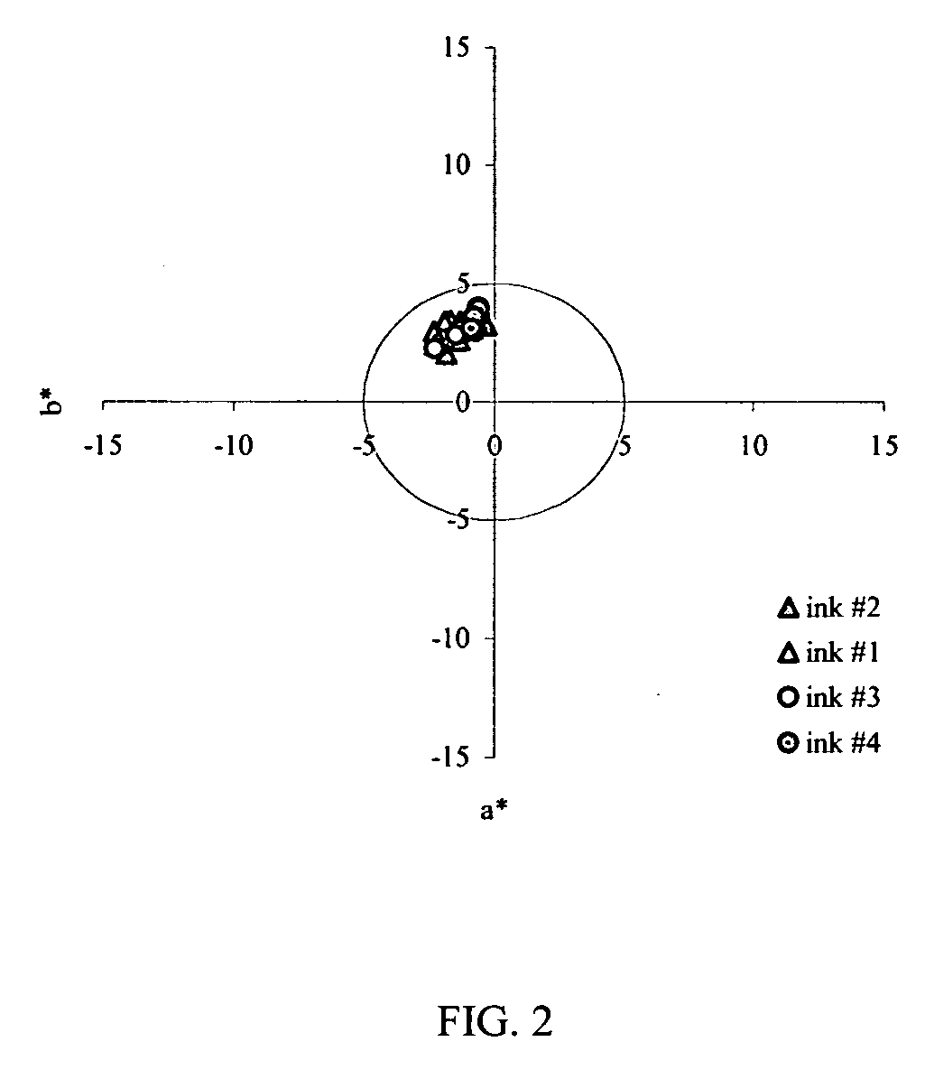
[0058] Inks used in the invention and control inks were prepared by simple mixing of the ingredients. After thorough mixing, each ink was filtered with a 0.2 micron filter. The inks shown in Table 1 were prepared.

TABLE 1ink #DyeWt. % dye in ink11st black dyePacified Reactive Black 31a2.402nd black dyeDuasyn ® NB-SFb Direct1.20yellow dyeYellow 86c0.4021st black dyePacified Reactive Black 31a2.522nd black dyeDuasyn ® NB-SFb1.28yellow dyeDirect Yellow 132d0.2031st black dyeAcid Black 52e3.202nd black dyeDuasyn ® NB-SFb0.40yellow dyeDirect Yellow 86c0.4041st black dyePacified Reactive Black 31a1.402nd black dyeIlford K-1334f2.00yellow dyeDirect Yellow 86c0.60

aavailable from Sensient Technical Colors, Inc. as a 10 wt. % dye solution in water

bavailable from Clariant Corp., a 10 wt. % dye solution in water

cavailable as a 10 wt. % dye solution in water from Sensient Technical Colors, Inc.

davailable as Pro-Jet ® Yellow 1G from Avecia, Inc., a 7.5 wt. % dye solution ...


PUM


Abstract

An ink jet ink comprising: a) at least one first metal complex black dye that when printed alone on a receiving element gives a CIELAB a* value>0 and at 1.0 Status A visual density; b) at least one second metal complex black dye that when printed alone on a receiving element gives a CIELAB a* value<0 and at 1.0 Status A visual density; and c) at least one yellow azo-aniline yellow dye or metal complex yellow dye or mixtures thereof.

Description


Claims


Application Information

Patent Timeline
Owner EASTMAN KODAK CO
Learn More