Photoconductive members

a technology of photoconductive and imaging members, applied in the field of imaging members, can solve the problems of non-uni formation of non-uniform and unacceptable, non-uniformity in the electrical properties of the imaging member, etc., and achieve excellent photosensitivity, prevent interaction, and excellent photosensitivity

Inactive Publication Date: 2006-07-11
XEROX CORP
View PDF13 Cites 16 Cited by
  • Summary
  • Abstract
  • Description
  • Claims
  • Application Information

AI Technical Summary

Benefits of technology

[0015]It is a feature of the present invention to provide imaging members thereof with many of the advantages illustrated herein.
[0016]Another feature of the present invention relates to the provision of layered photoresponsive imaging members with excellent photosensitivity to near infrared radiations, and wherein light wavelengths emitted in the visible region are absorbed in the overcoating layer and prevented from interacting with, or entering into, in embodiments, the photogenerating layer.
[0017]Yet another feature of the present invention relates to the provision of layered photoresponsive imaging members with excellent photosensitivity to near infrared radiations, and wherein light wavelengths emitted in the blue region are absorbed in the overcoating layer containing certain yellow dyes, and which light is substantially prevented from interacting with the photogenerating layer. Blue light is the primary cause of light shock, which refers, for example, to a change in the photoreceptor's electrical properties after prolonged exposure to room light.
[0020]Aspects of the present invention relate to a photoconductive imaging member comprised of a supporting substrate, a photogenerating layer, a charge transport layer, and an overcoating layer, and wherein the overcoating layer is, for example, comprised of a polymer, such as LUCKAMIDE®, and a yellow dye wherein the overcoating layer substantially prevents undesirable light of, for example, a wavelength of about equal to or less than about 700 nanometers, such as from about 400 to about 500 nanometers from interaction with the photogenerating layer; a photoconductive member with a photogenerating layer of a thickness of from about 0.1 to about 10 microns, a transport layer of a thickness of from about 5 to about 100 microns; a photoconductive member wherein the dye component is present in an amount of from about 0.1 to about 5 weight percent; an imaging method and an imaging apparatus containing a charging component, a development component, a transfer component, and a fixing component, and wherein the apparatus contains a photoconductive imaging member comprised of a supporting substrate, and thereover a layer comprised of a photogenerator pigment and a charge transport layer, and thereover an overcoating layer containing the yellow dye illustrated herein; a photoconductive imaging member comprised of a supporting substrate, a photogenerating layer with a top overcoating layer containing a yellow dye component that prevents light of a wavelength of about equal to or about less than 700 nanometers from interaction with the photogenerating layer; a member wherein the photogenerating layer is of a thickness of from about 0.1 to about 10 microns, and the transport layer is of a thickness of from about 40 to about 75 microns; a member wherein the dye component is present in an amount of from about 0.1 to about 7 weight percent; a member wherein the photogeneratin layer contains a photogenerating pigment present in an amount of from about 5 to about 95 weight percent, and wherein the yellow dye component is present in an amount of from about 0.1 to about 1 weight percent; a member wherein the thickness of the photogenerator layer is from about 0.1 to about 4 microns; a member wherein the photogenerating layer contains a polymer binder; a member wherein the binder is present in an amount of from about 50 to about 90 percent by weight, and wherein the total of all layer components is about 100 percent; a member wherein the photogenerating component is a hydroxygallium phthalocyanine that absorbs light of a wavelength of from about 370 to about 950 nanometers; an imaging member wherein the supporting substrate is comprised of a conductive substrate comprised of a metal; an imaging member wherein the conductive substrate is aluminum, aluminized polyethylene terephthalate or titanized polyethylene terephthalate; an imaging member wherein the photogenerating resinous binder is selected from the group consisting of polyesters, polyvinyl butyrals, polycarbonates, polystyrene-b-polyvinyl pyridine, and polyvinyl formulas; an imaging member wherein the photogenerator is a metal free phthalocyanine; an imaging member wherein the charge transport layer comprises

Problems solved by technology

Thus, for example, during belt replacement or machine maintenance, nonuniform exposure of a photoreceptor to room light can result in nonuniformity in the electrical properties of the imaging member.
A difference in electrical properties between exposed areas of an imaging member is undesirable because it can cause nonuniform image potentials which in turn results in the formation of nonuniform and unacceptable in many instances toner images when the light shocked imaging member is subsequently utilized for electrophotographic imaging.
Thus, for example, during belt replacement or machine maintenance, nonuniform exposure of the photoreceptor to room light can result in nonuniformity in the electrical properties of the imaging member.
A difference in electrical properties between exposed areas of an imaging member is undesirable because it can cause nonuniform image potentials which can result in the formation of nonuniform toner images when the light shocked imaging member is subsequently utilized for electrophotographic imaging.
The light shock problem can be particularly serious in imaging members containing phthalocyanine particles, such as hydroxygallium phthalocyanine or alkoxygallium phthalocyanine, as photogenerating pigments.

Method used


Image

  • Photoconductive members
  • Photoconductive members
  • Photoconductive members

Examples


example ii

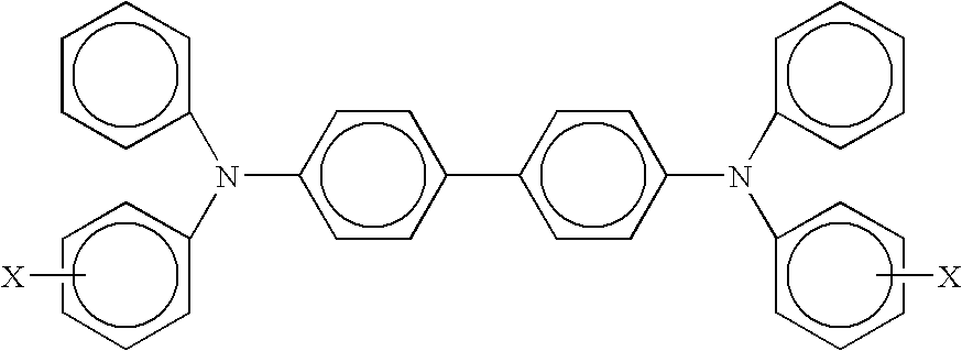
[0044]A hydroxygallium phthalocyanine (HOGaPc (V)) charge generator layer was prepared by repeating the processes of Example I. A transport layer solution was then generated by mixing 10 grams of N,N′-diphenyl-N,N′-bis(3-methylphenyl)-1,1-biphenyl-4,4′-diamine (TPD), 10 grams of polycarbonate resin (available as MAKROLON 5705® from Bayer A.G.), and 133 grams of methylene chloride. The solution was stirred overnight (about 18 to about 20 hours throughout) until a complete solution was obtained. The resulting transport solution was coated onto the above photogenerating layer using a Bird film applicator with a 4 mil gap.

[0045]The above transport layer was then overcoated with a mixture of 0.7 gram of a polyamide containing methoxymethyl groups (LUCKAMIDE® 5003 available from Dai Nippon Ink), 0.3 gram of ELVAMIDE® 8063 (available from E.I. DuPont), methanol (3.5 grams) and 1-propanol (3.5 grams) from a 2 ounce amber bottle and warmed with magnetic stirring in a water bath at about 60° ...

example iii

[0048]A hydroxygallium phthalocyanine (HOGaPc (V)) charge generator layer was prepared following the processes as described in Example I. A transport layer solution was then generated by mixing 10 grams of N,N′-diphenyl-N,N′-bis(3-methylphenyl)-1,1-biphenyl-4,4′-diamine (TPD), 10 grams of polycarbonate resin (available as MAKROLON® 5705 from Bayer A.G.), and 133 grams of methylene chloride. The resulting mixture was stirred overnight until a complete solution was obtained. The transport solution was coated onto the above photogenerating layer using a Bird film applicator with a 4 mil gap. The resulting member was dried at 100° C. in a forced air oven for 30 minutes.

[0049]The above transport layer was then overcoated with a mixture of 0.7 gram of a polyamide containing methoxymethyl groups (LUCKAMIDE® 5003 available from Dai Nippon Ink), 0.3 gram of ELVAMIDE® 8063 (available from E.I. DuPont), methanol (3.5 grams) and 1-propanol (3.5 grams) from a 2 ounce amber bottle and warmed with...

example iv

[0052]A hydroxygallium phthalocyanine (HOGaPc (V)) charge generator layer was prepared by following the processes as described in Example I. A hole transport layer solution was then generated by mixing 10 grams of N,N′-diphenyl-N,N′-bis(3-methylphenyl)-1,1-biphenyl-4,4′-diamine (TPD), 10 grams of polycarbonate resin (available as MAKROLON® 5705 from Bayer A.G.), and 133 grams of methylene chloride. The mixture resulting was stirred overnight until a complete solution was affected. The transport solution was coated onto the above photogenerating layer using a Bird film applicator with a 4 mil gap. The resulting member was dried at 100° C. in a forced air oven for 30 minutes.

[0053]The above transport layer was then overcoated with a mixture of 0.7 gram of a polyamide containing methoxymethyl groups (LUCKAMIDE® 5003 available from Dai Nippon Ink), 0.3 gram of ELVAMIDE® 8063 (available from E.I. DuPont), methanol (3.5 grams) and 1-propanol (3.5 grams) from a 2 ounce amber bottle and war...


PUM


Abstract

A photoconductive imaging member containing a supporting substrate, a photogenerating layer, a charge transport layer, and in contact with the charge transport layer a layer comprised of a polymer and a yellow dye of the formula

Description

[0001]This is a divisional of U.S. application Ser. No. 10 / 429,550 filed May 5, 2003, now U.S. Pat. No. 6,919,154 issued Jul. 19, 2005, by the same inventors, and claims priority therefrom.RELATED PATENTS[0002]Illustrated in U.S. Pat. No. 6,713,220 on Photoconductive Members, the disclosure of which is totally incorporated herein by reference, is a photoconductive imaging member comprised of a supporting substrate, a photogenerating layer and a charge transport layer, and wherein the charge transport layer contains a component that substantially prevents light of a wavelength of about equal to or about less than 700 nanometers from interaction with the photogenerating layer.[0003]Illustrated in U.S. Pat. No. 5,756,245, the disclosure of which is totally incorporated herein by reference, is a photoconductive imaging member comprised of a hydroxygallium phthalocyanine photogenerator layer, a charge transport layer, a barrier layer, a photogenerator layer comprised of a mixture of bisb...

Claims


Application Information

Patent Timeline
Patent Type & Authority Patents(United States)
IPC IPC(8): G03G5/147G03G5/06
CPCG03G5/0614G03G5/14765G03G5/14708G03G5/0677G03G5/061443
Inventor FULLER, TIMOTHY J.MISHRA, SATCHIDANANDYANUS, JOHN F.HORGAN, ANTHONY M.FOLEY, GEOFFREY M. T.YUH, HUOY-JENRENFER, DALE S.TONG, YUHUADINH, KENNY-TUAN T.SILVESTRI, MARKUS R.GRAHAM, JOHN F.
Owner XEROX CORP
Why Eureka
Try Eureka