

Optical lens system for taking image
a technology of optical lens and image, applied in the field of optical lens system for taking image, can solve the problems of reducing the degree of freedom of the optical system, reducing the length of the whole optical system, and difficult control of the gluing process of glass lens elements
- Summary
- Abstract
- Description
- Claims
- Application Information
AI Technical Summary
Benefits of technology
Problems solved by technology
Method used
Image

Examples
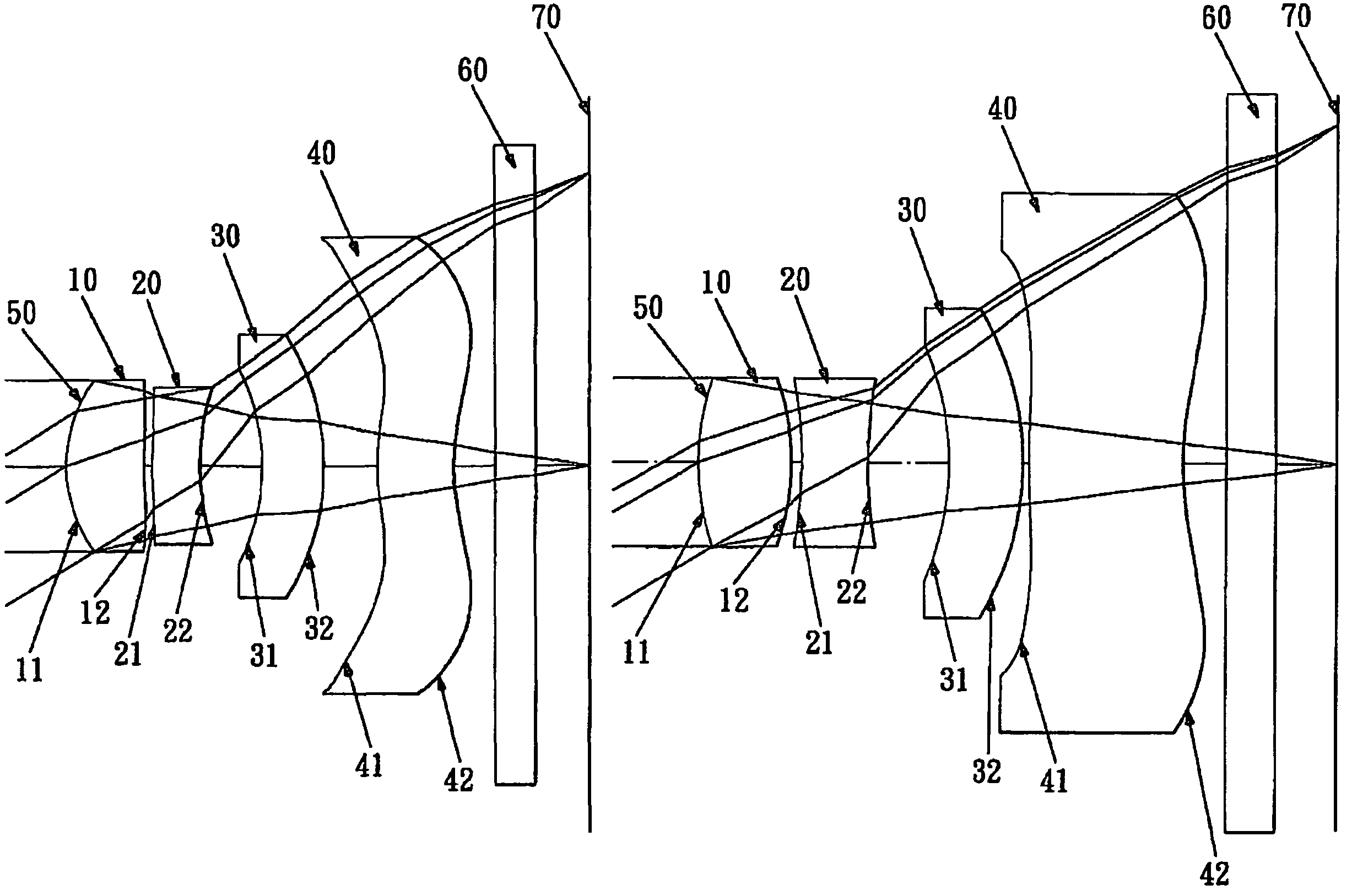
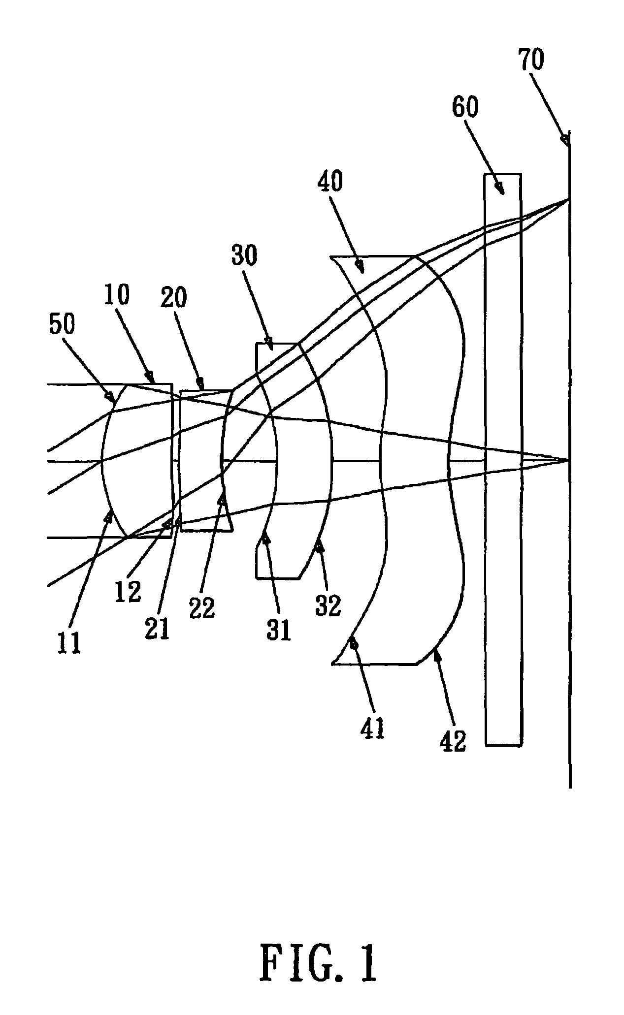
first embodiment
[0051]In the present optical lens system for taking image, the focal length of the first lens element is f1, the focal length of the second lens element is f2, the focal length of the third lens element is f3, the focal length of the fourth lens element is f4, the focal length of the first and second lens elements combined is f12, the focal length of the optical lens system for taking image is f, and they satisfy the relations:
f=3.56 mm;
f / f1=1.50;
f / f2=−0.64;
f / f3=−0.003;
f / f4=−0.39;
f / f12=1.07.
[0052]In the first embodiment of the present optical lens system for taking image, the Abbe number of the first lens element is V1, the Abbe number of the second lens element is V2, the Abbe number of the fourth lens element is V4, and they satisfy the relations:
V2=23.4;
V4=55.8;
[(V1+V4) / 2]−V2=32.8.
[0053]In the first embodiment of the present optical lens system for taking image, the radius of curvature of the object-side surface of the first lens element is R1, the focal length of the optical len...
second embodiment
[0072]In the present optical lens system for taking image, the focal length of the first lens element is f1, the focal length of the second lens element is f2, the focal length of the third lens element is f3, the focal length of the fourth lens element is f4, the focal length of the first and second lens elements combined is f12, the focal length of the optical lens system for taking image is f, and they satisfy the relations:
f=3.48 mm;
f / f1=1.80;
f / f2=−1.12;
f / f3=−0.10;
f / f4=−0.10;
f / f12=0.98.
[0073]In the second embodiment of the present optical lens system for taking image, the Abbe number of the first lens element is V1, the Abbe number of the second lens element is V2, the Abbe number of the fourth lens element is V4, and they satisfy the relations:
V2=30.2;
V4=55.8;
[(V1+V4) / 2]−V2=26.0.
[0074]In the second embodiment of the present optical lens system for taking image, the radius of curvature of the object-side surface of the first lens element is R1, the focal length of the optical le...
third embodiment
[0093]In the present optical lens system for taking image, the focal length of the first lens element is f1, the focal length of the second lens element is f2, the focal length of the third lens element is f3, the focal length of the fourth lens element is f4, the focal length of the first and second lens elements combined is f12, the focal length of the optical lens system for taking image is f, and they satisfy the relations:
f=3.37 mm;
f / f1=1.70;
f / f2=−0.93;
f / f3=−0.10;
f / f4=−0.10;
f / f12=1.03.
[0094]In the third embodiment of the present optical lens system for taking image, the Abbe number of the first lens element is V1, the Abbe number of the second lens element is V2, the Abbe number of the fourth lens element is V4, and they satisfy the relations:
PUM
 Abstract
Description
Claims
Application Information