

Image-capturing lens assembly
a technology of image-capturing lens and assembly, which is applied in the field of image-capturing lens assembly, can solve the problems of reducing the total track length of the system, reducing the sensitivity of the optical system, and the three-element lens has become insufficient for a high-end imaging lens module, so as to improve the sensitivity of the optical system, and reduce the size of the lens assembly
- Summary
- Abstract
- Description
- Claims
- Application Information
AI Technical Summary
Benefits of technology
Problems solved by technology
Method used
Image

Examples
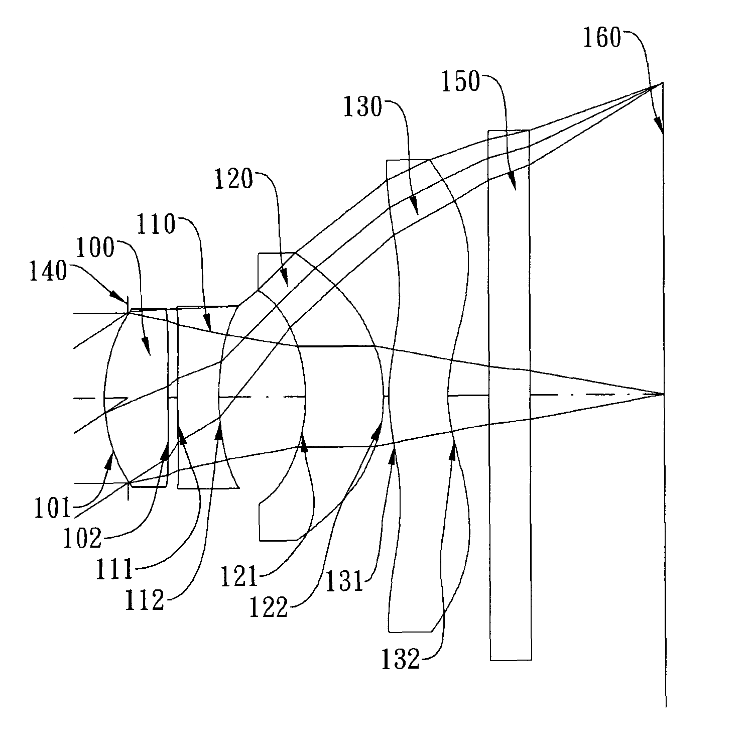
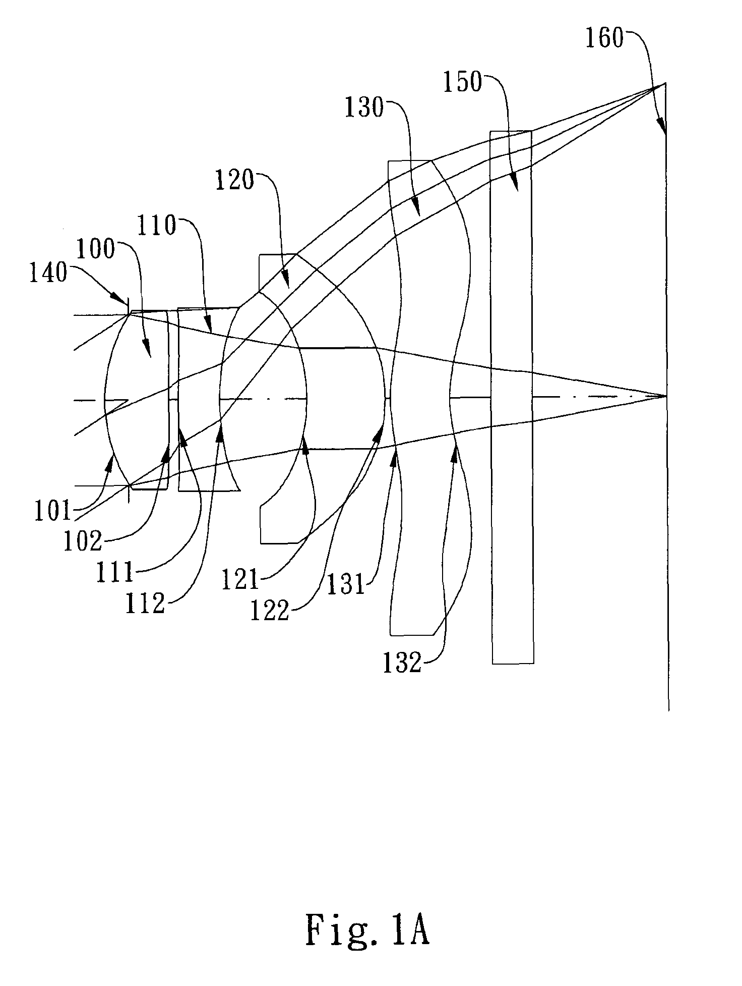
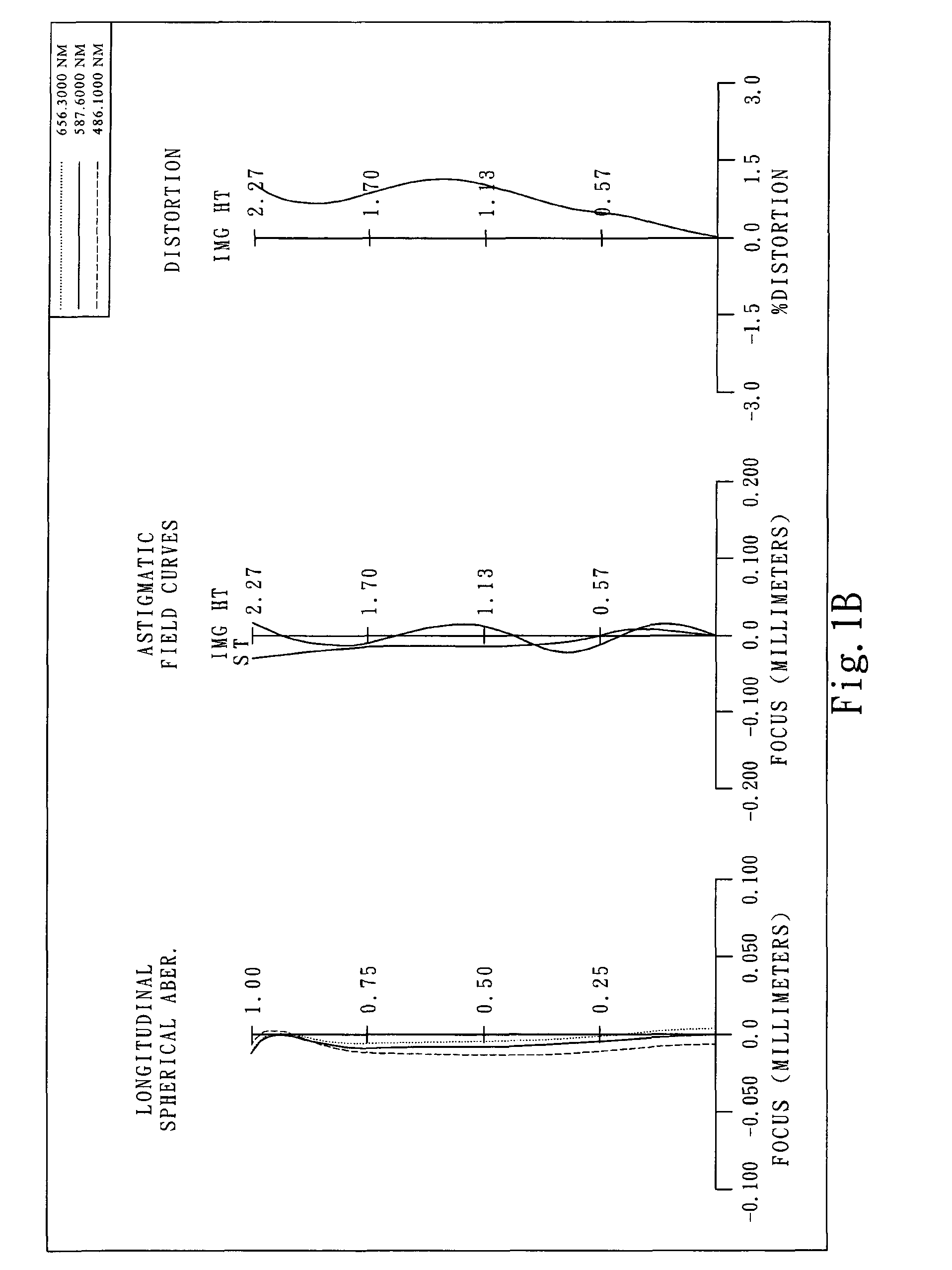
first embodiment
[0068]In the present image-capturing lens assembly, the focal length of the image-capturing lens assembly is f, and it satisfies the relation: f=3.53 (mm).
[0069]In the first embodiment of the present image-capturing lens assembly, the f-number of the image-capturing lens assembly is Fno, and it satisfies the relation: Fno=2.85.
[0070]In the first embodiment of the present image-capturing lens assembly, half of the maximal field of view of the image-capturing lens assembly is HFOV, and it satisfies the relation: HFOV=32.5 deg.
[0071]In the first embodiment of the present image-capturing lens assembly, the focal length of the image-capturing lens assembly is f, the focal length of the first lens element 100 is f1, and they satisfy the relation: f / f1=1.67.
[0072]In the first embodiment of the present image-capturing lens assembly, the focal length of the image-capturing lens assembly is f, the focal length of the third lens element 120 is f3, and they satisfy the relation: f / f3=0.33.
[0073...
second embodiment
[0087]In the present image-capturing lens assembly, the focal length of the image-capturing lens assembly is f, and it satisfies the relation: f=2.91 (mm).
[0088]In the second embodiment of the present image-capturing lens assembly, the f-number of the image-capturing lens assembly is Fno, and it satisfies the relation: Fno=2.40.
[0089]In the second embodiment of the present image-capturing lens assembly, half of the maximal field of view of the image-capturing lens assembly is HFOV, and it satisfies the relation: HFOV=31.6 deg.
[0090]In the second embodiment of the present image-capturing lens assembly, the focal length of the image-capturing lens assembly is f, the focal length of the first lens element 200 is f1, and they satisfy the relation: f / f1=1.66.
[0091]In the second embodiment of the present image-capturing lens assembly, the focal length of the image-capturing lens assembly is f, the focal length of the third lens element 220 is f3, and they satisfy the relation: f / f3=0.92.
[...
third embodiment
[0106]In the present image-capturing lens assembly, the focal length of the image-capturing lens assembly is f, and it satisfies the relation: f=6.14 (mm).
[0107]In the third embodiment of the present image-capturing lens assembly, the f-number of the image-capturing lens assembly is Fno, and it satisfies the relation: Fno=2.83.
[0108]In the third embodiment of the present image-capturing lens assembly, half of the maximal field of view of the image-capturing lens assembly is HFOV, and it satisfies the relation: HFOV=30.7 deg.
[0109]In the third embodiment of the present image-capturing lens assembly, the focal length of the image-capturing lens assembly is f, the focal length of the first lens element 300 is f1, and they satisfy the relation: f / f1=1.16.
[0110]In the third embodiment of the present image-capturing lens assembly, the focal length of the image-capturing lens assembly is f, the focal length of the third lens element 320 is f3, and they satisfy the relation: f / f3=0.72.
[0111...
PUM
 Abstract
Description
Claims
Application Information