Well control and monitoring system using high temperature electronics

Inactive Publication Date: 2005-04-28
HONEYWELL INT INC
View PDF6 Cites 15 Cited by
  • Summary
  • Abstract
  • Description
  • Claims
  • Application Information

AI Technical Summary

Benefits of technology

[0006] In accordance with one aspect of the present invention, a well control and monitoring system for the control and monitoring of a plurality of wells comprises a remote control center, a plurality of surface control and monitoring systems, and a plurality of down hole monitoring and control systems. Each of the wells is provided with a corresponding one of the surface control and monitoring systems, and the surface control and monitoring systems are in communication with the remote control center. Each of the wells is also provided with at least one of the down hole monitoring and control systems, and each of the down hole monitoring and control systems is in communication with at least one of the surface control and monitoring systems. Moreover, each of the down hole monitoring and control systems comprises a non-cooled, high temperature controller arranged to perform monitoring and control functions within a corresponding one of the wells.
[0007] In accordance with another asp

Problems solved by technology

The control and monitoring of oil and gas wells have become increasingly complex.
Moreover, the wells themselves have become increasingly more complex.
It has been difficult to implement down hole electronic control and monitoring of wells because of the difficult temperature environment within the wells.
Unless cooling is provided for the down hole electronic control an

Method used


Image

  • Well control and monitoring system using high temperature electronics
  • Well control and monitoring system using high temperature electronics

Examples


Embodiment Construction

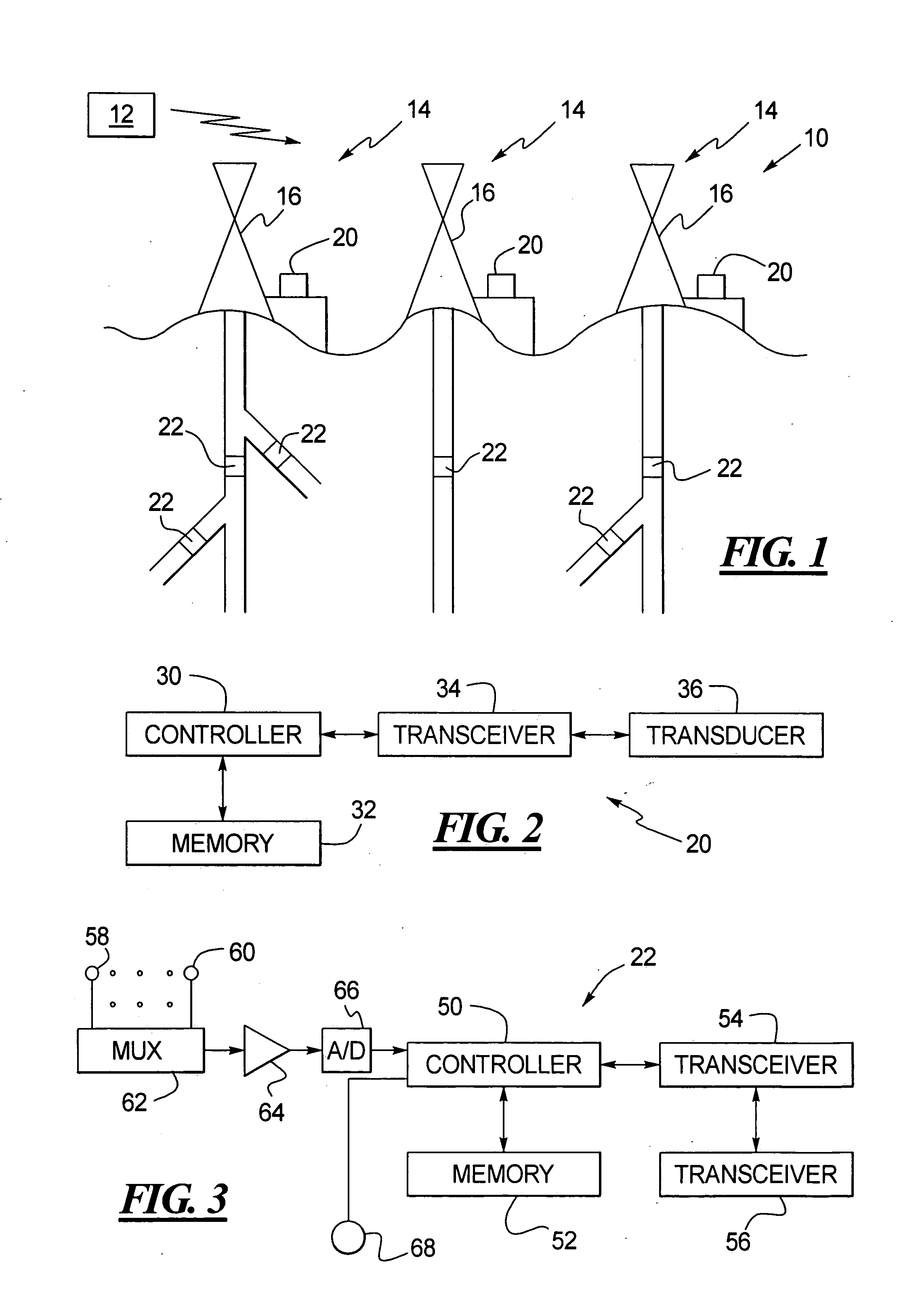
[0013] As shown in FIG. 1, a monitoring and control system 10 includes a remote control center 12 that communicates with a plurality of wells 14. Although only three wells are shown in FIG. 1, it should be understood that the monitoring and control system 10 may include any number of wells. Because the wells 14 may be geographically dispersed, the remote-control center 12 remotely communicates with the wells 14 using cellular transmissions, satellite transmissions, telephone lines, and / or the like.

[0014] Each of the wells 14 is provided with a corresponding well platform 16 located at the surface of the corresponding one of the wells 14. As shown, the wells 14 extend from the well platforms 16 downwardly into the earth. However, it should be understood that, while the wells 14 are shown over land, one or more of the wells 14 may instead extend down from offshore platforms or from platforms located on other planets.

[0015] If desired, each of the wells 14 may be divided into a plura...


PUM


Abstract

A remote control center controls and monitors a plurality of wells. A surface control and monitoring system is located at each of the wells, and each of the surface control and monitoring systems is in communication with a remote control center. Also, a down hole monitoring and control system is provided within each of the wells, and each of the down hole monitoring and control systems is in communication with at least one of the surface control and monitoring systems. Each of the down hole monitoring and control systems comprises non-cooled, high temperature electronic equipment that can withstand the high temperature environment within the corresponding well.

Description

TECHNICAL FIELD OF THE INVENTION [0001] The present invention relates to monitoring and / or control systems that are used in high temperature down hole applications. BACKGROUND OF THE INVENTION [0002] The control and monitoring of oil and gas wells have become increasingly complex. For example, wells under the control of a single company are being drilled throughout the world. Therefore, the need for central control and monitoring of wells that are widely dispersed geographically is becoming increasingly important. Such central control and monitoring requires the communication of sensor and logging information from the wells to the central controller and the communication of control information from the central controller to the wells. [0003] Moreover, the wells themselves have become increasingly more complex. For example, well holes are being drilled with multiple branches and are being divided into multiple production zones that discretely produce fluid or gas in either common or ...

Claims


Application Information

Patent Timeline
IPC IPC(8): E21B47/12
CPCE21B47/12E21B41/0035E21B47/14
Inventor MALLISON, EDGAR R.STRATTON, THOMAS G.
Owner HONEYWELL INT INC
Why Eureka
Try Eureka