Casting preforms for optical fibres

a technology of optical fibres and preforms, applied in the field of preparing preforms for optical fibres, can solve the problems of less known use of photonic band gap effect and more complex structures that have now been developed, and achieve the effect of difficult or expensive production

Inactive Publication Date: 2005-04-28
THE UNIV OF SYDNEY +2
View PDF4 Cites 152 Cited by
  • Summary
  • Abstract
  • Description
  • Claims
  • Application Information

AI Technical Summary

Benefits of technology

[0019] The above described technique and its preferred embodiments provides a number of significant advantages over the prior art. They include the opportunity to produce holey fibre preforms with discrete elements, eg. air holes, of various shapes and sizes, complex fibre shapes which are currently difficult or expensive to produce using conventional techniques, eg. multiple core structures, ability to produce holey fibres from a wide range of optically suitable materials than is currently used, a more efficient mechanism for producing holey optical fibres and preforms, and the opportunity to provide continuous production of such products.

Problems solved by technology

More complex structures have now been developed.
However, it was soon realised that the fibres also operated by simple index guidance due to the high refractive index of the core region or defect compared to the effective index of the surrounding air holes or cladding microstructure.
While the performance of crystal fibres via index guiding is well known, their use for transmission via the photonic band gap effect is not as well known.

Method used


Image

  • Casting preforms for optical fibres
  • Casting preforms for optical fibres

Examples


Embodiment Construction

)

[0022] A number of preferred aspects of the invention will now be described, by way of example only.

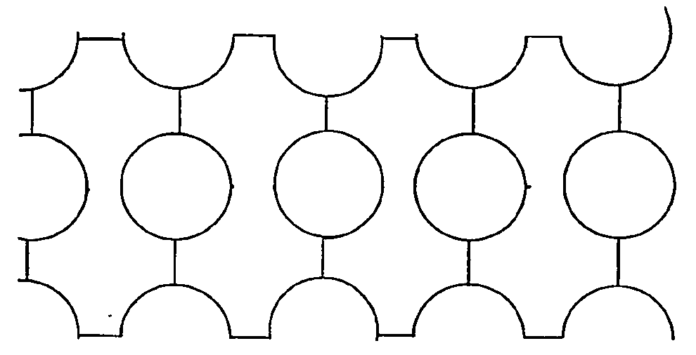
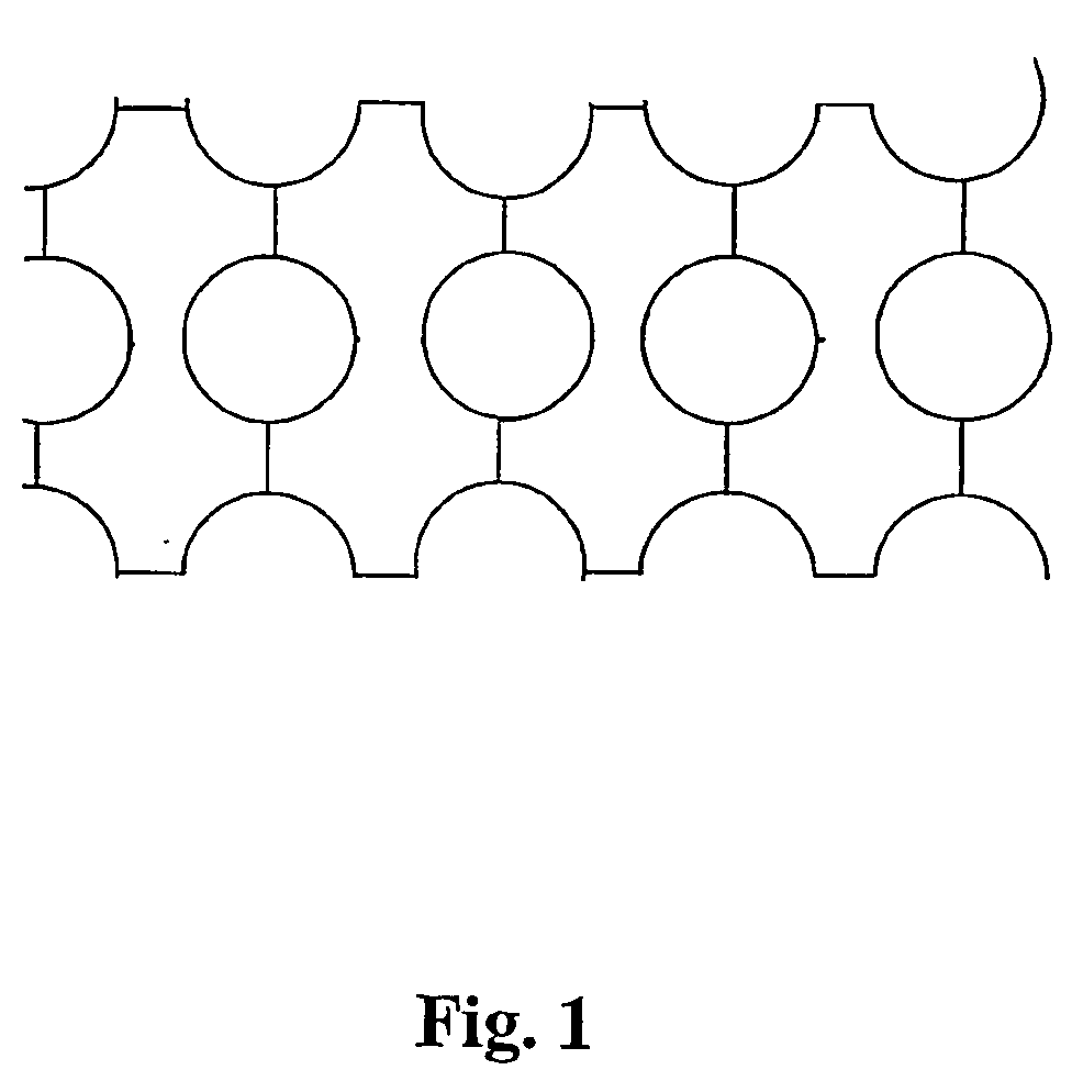
[0023] This invention provides a method of producing structured polymer preforms, capillaries or canes suitable for subsequent drawing to form a holey polymer fibre. The entire preform may be cast as a unitary body, or canes and capillaries may be individually cast and combined to produce a polymer preform.

[0024] The possibility of casting preforms allows an almost limitless variety of structures to be produced. These may be either a complete preform for photonic crystal fibre, or canes or capillaries that allow such a preform to be constructed.

[0025] A key issue to be addressed in casting or moulding a holey structure in polymers is that polymers are generally more dense than their corresponding monomeric solutions. This means that in general, although not in every case, shrinkage of the order of 4-8% occurs during polymerisation. This has the result of shrinking the resulting po...


PUM

PropertyMeasurementUnit
shrinkageaaaaaaaaaa
glass transition temperatureaaaaaaaaaa
thermal expansion coefficientsaaaaaaaaaa

Abstract

This invention relates to a method of preparing a preform for an optical fibre, and more particularly to a method of preparing a preform for a polymer holey optical fibre. The invention provides a method of preparing a preform for manufacture of a polymer holey optical fibre comprising casting a preform body in a mould from a suitable material, said mould including at least one protrusion adapted to form a corresponding hole within the preform, and subsequently separating the preform body and mould. The invention also provides a method of preparing a preform for manufacture of a polymeric holey optical fibre comprising separately casting one or more elements of a preform in respective mould(s) from a suitable material, and separating said elements from said respective mould(s) and combining said elements to construct a preform having a plurality of holes therein, each hole being formed in an element or formed by the combination of two or more elements.

Description

FIELD OF THE INVENTION [0001] This invention relates to a method of preparing a preform for an optical fibre, and more particularly to a method of preparing a preform for a polymer holey optical fibre. BACKGROUND TO TH INVENTION [0002] Any discussion of the prior art throughout the specification should in no way be considered as an admission that such prior art is widely known or forms part of common general knowledge in the field. [0003] In the late 1990's, Philip Russell from the University of Bath, United Kingdom and his co-workers developed optical fibres which comprised micro structured silica with a series of several hundred air holes running along its length. [0004] These fibres were sometimes referred to as holey fibres and more lately as crystal fibres due to the complex lattice microstructure of the air holes. Technically, such holey or crystal fibres do not include a “core” or “cladding” as the terms are used when referring to conventional graded index optical fibres. In ...

Claims


Application Information

Patent Timeline
Patent Type & Authority Applications(United States)
IPC IPC(8): B29C33/00B29C33/38B29D11/00G02B6/02
CPCB29C33/0033B29C33/38B29D11/00721Y10T428/24273G02B6/02033G02B6/02314B29L2011/0075
Inventor LARGE, MARYANNE CANDIDA JANEZAGARI, JOSEPHCANNING, JOHNRYAN, TOMVAN EIJKELENBORG, MARTIN ALEXANDERGORINGE, NILMINI SUREKAISSA, NADER
Owner THE UNIV OF SYDNEY
Why Eureka
Try Eureka