System and method for pumping fluid using a pump cassette

a technology of pump cassette and fluid, which is applied in the direction of positive displacement liquid engine, liquid fuel engine, instruments, etc., can solve the problems of affecting the precision with which the cassette chamber is expanded and contracted, and the amount of fluid pumped by the cassette can be inaccura

Inactive Publication Date: 2005-05-05
DEKA PROD LLP
View PDF99 Cites 105 Cited by
  • Summary
  • Abstract
  • Description
  • Claims
  • Application Information

AI Technical Summary

Benefits of technology

[0015] In accordance with further related embodiments of the invention, the system may include a cassette receptacle for receiving the pump cassette. The force assembly may be movably coupled to the control assembly to allow access to the cassette receptacle. For e

Problems solved by technology

Improper spacing, sealing, or alignment between the control assembly and cassette undesirably can impact the precision with wh

Method used


Image

  • System and method for pumping fluid using a pump cassette
  • System and method for pumping fluid using a pump cassette
  • System and method for pumping fluid using a pump cassette

Examples


Embodiment Construction

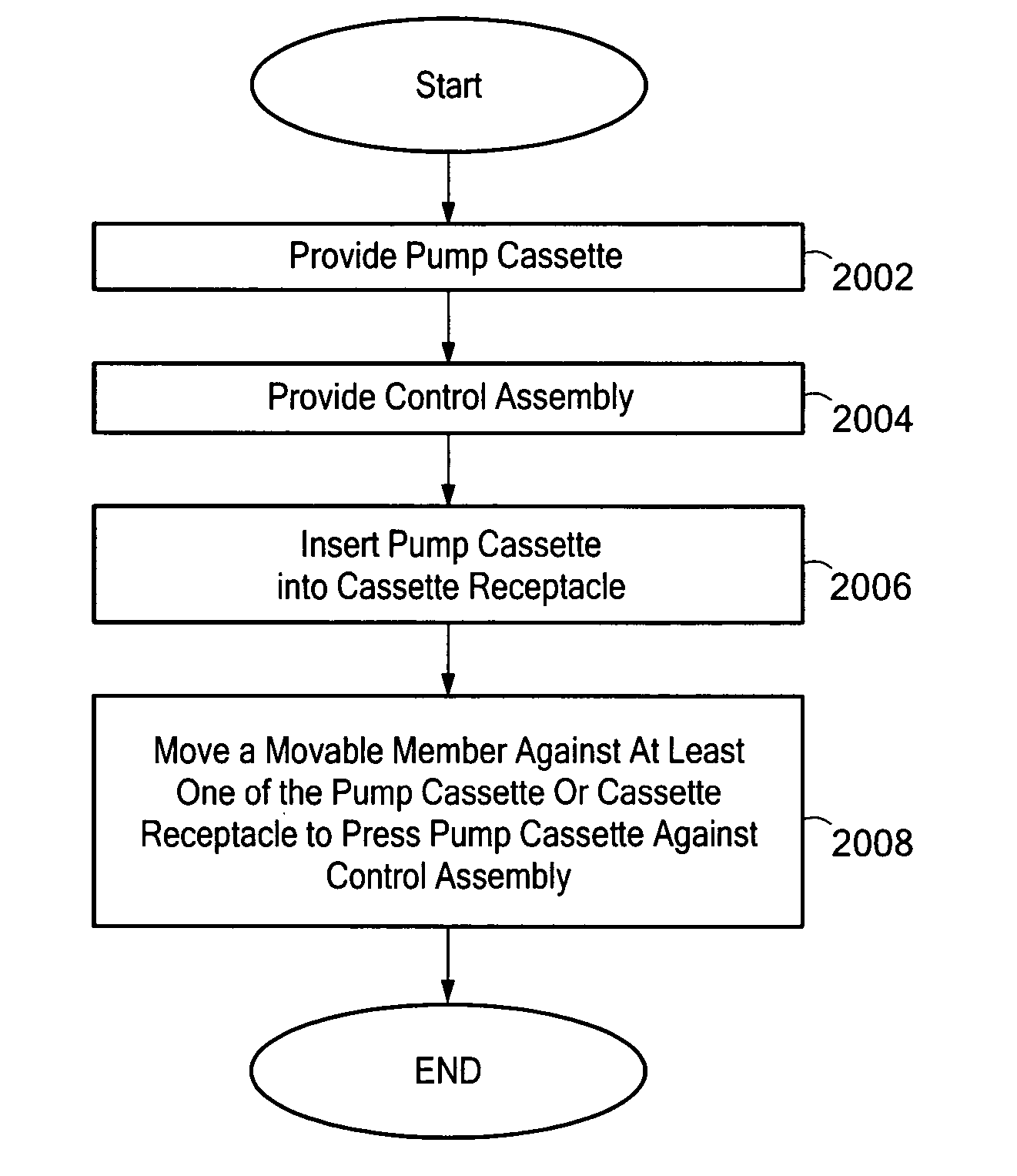
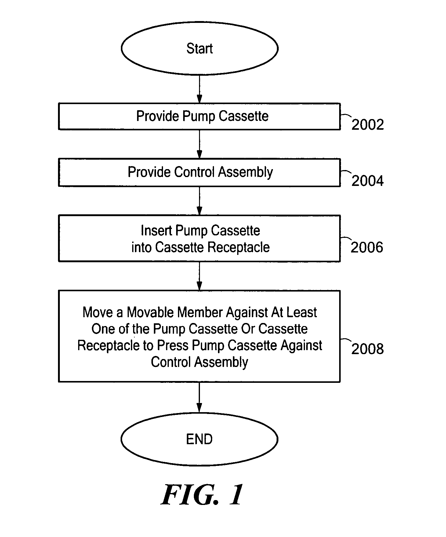
[0054] Illustrative embodiments of the present invention pump fluid using a pump cassette. The pump cassette, which is preferably pneumatically operated by a control assembly, includes various combinations of membrane-based chambers and valves. During use, the control assembly is pressed in close face-to-face contact against the pump cassette, and precisely actuates the membrane-based chambers and valves to regulate fluid flow through the cassette. A force assembly ensures that an adequately sealed, face-to-face contact is maintained between the control assembly and the pump cassette. To those ends, the force assembly includes a movable member capable of applying a continuous force to the pump cassette to press the pump cassette against the control assembly. Details of various embodiments are discussed below.

[0055]FIG. 1 is a process flow diagram describing a process 2000 for pumping of fluid using a pump cassette, in accordance with one embodiment of the invention. Beginning in bl...


PUM

PropertyMeasurementUnit
Forceaaaaaaaaaa

Abstract

A system and method for pumping fluid using a pump cassette. The system includes a control assembly for operating the pump cassette. A force assembly having a movable member is capable of applying force to the pump cassette to press the pump cassette against the control assembly. The movable member may be an expandable member, such as a bladder.

Description

CROSS-REFERENCE TO RELATED APPLICATION(S) [0001] The present application may include subject matter related to one or more of the following commonly-owned United States patent applications, each of which was filed on even date herewith and is hereby incorporated herein by reference in its entirety: [0002] U.S. patent application No. ______ entitled SYSTEM, DEVICE, AND METHOD FOR MIXING A SUBSTANCE WITH A LIQUID (referred to herein as “Application D70”); [0003] U.S. patent application No. ______ entitled SYSTEM, DEVICE, AND METHOD FOR MIXING LIQUIDS (referred to herein as “Application D71”); [0004] U.S. patent application No. ______ entitled TWO-STAGE MIXING SYSTEM, APPARATUS, AND METHOD (referred to herein as “Application D72”); [0005] U.S. patent application No. ______ entitled DOOR LOCKING MECHANISM (referred to herein as “Application D74”); [0006] U.S. patent application No. ______ entitled BEZEL ASSEMBLY FOR PNEUMATIC CONTROL (referred to herein as “Application D75”); [0007] U.S...

Claims


Application Information

Patent Timeline
IPC IPC(8): A61L2/00A61L2/24A61M1/02A61M1/36B01F25/60F04B1/00F04B43/073F04B43/08F04B43/12F04B45/06G05D11/13
CPCA61L2/0088Y10T29/53A61M1/0272A61M1/0281A61M1/3687B01F3/0865B01F3/088B01F5/0077B01F5/12B01F13/1013B01F13/1016B01F15/0202B01F15/0475B01F2015/0221G05D11/132F04B53/16A61M1/0213A61L2/24A61M2205/125Y10T137/0352Y10T137/0329Y10T137/86131Y10T137/87652Y10T292/0911Y10T292/212Y10T292/438F04B43/06B01F23/451B01F23/49B01F25/105B01F25/60B01F33/811B01F33/81B01F35/711B01F35/715B01F35/8823Y02A50/30A61M1/36225F04B53/22F04B43/0009F04B13/02F04B23/06F04B53/06F04B23/02F04B49/22
Inventor LANIGAN, RICHARD J.DALE, JAMES D.
Owner DEKA PROD LLP
Why Eureka
Try Eureka