Electronically programmable multimode circuit

a multi-mode, electrically programmable technology, applied in pulse manipulation, gated amplifiers, pulse techniques, etc., can solve the problems of fixed topology and prior art not addressing the situation, and achieve the effect of improving the ability to focus the antenna beam width, improving the ability to control gain instead of loss, and fine resolution

a multi-mode, electrically programmable technology, applied in pulse manipulation, gated amplifiers, pulse techniques, etc., can solve the problems of fixed topology and prior art not addressing the situation, and achieve the effect of improving the ability to focus the antenna beam width, improving the ability to control gain instead of loss, and fine resolution

US20050099222A1Active Publication Date: 2005-05-12NORTHROP GRUMMAN SYST CORP

Image

  • Electronically programmable multimode circuit
  • Electronically programmable multimode circuit
  • Electronically programmable multimode circuit

Examples


Embodiment Construction

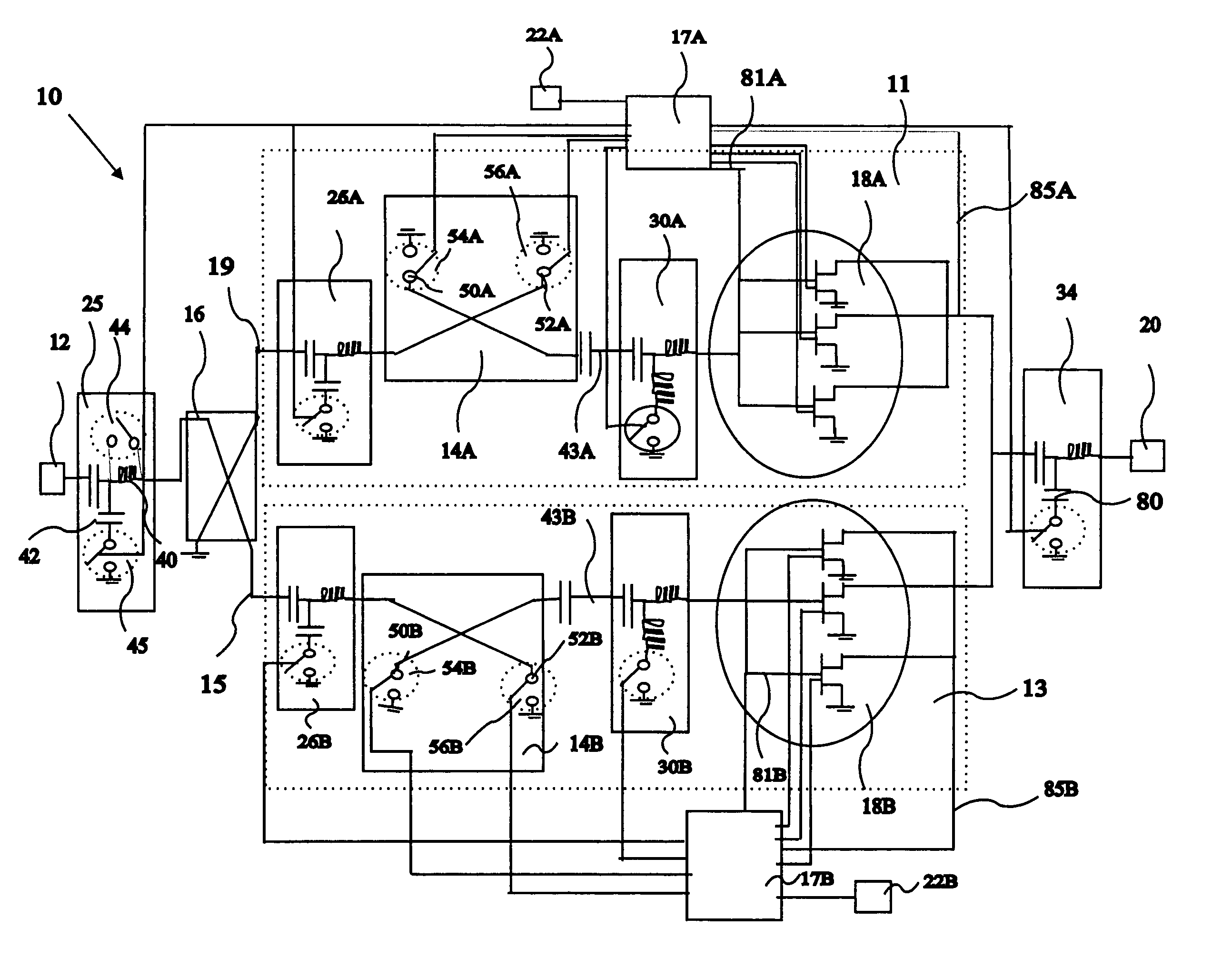
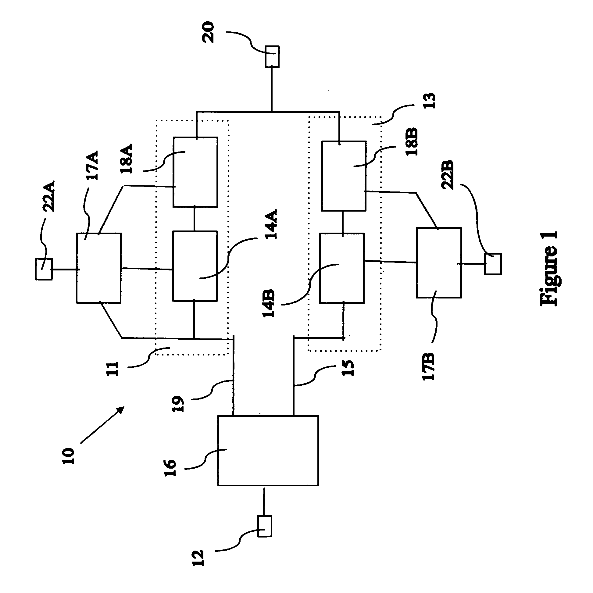
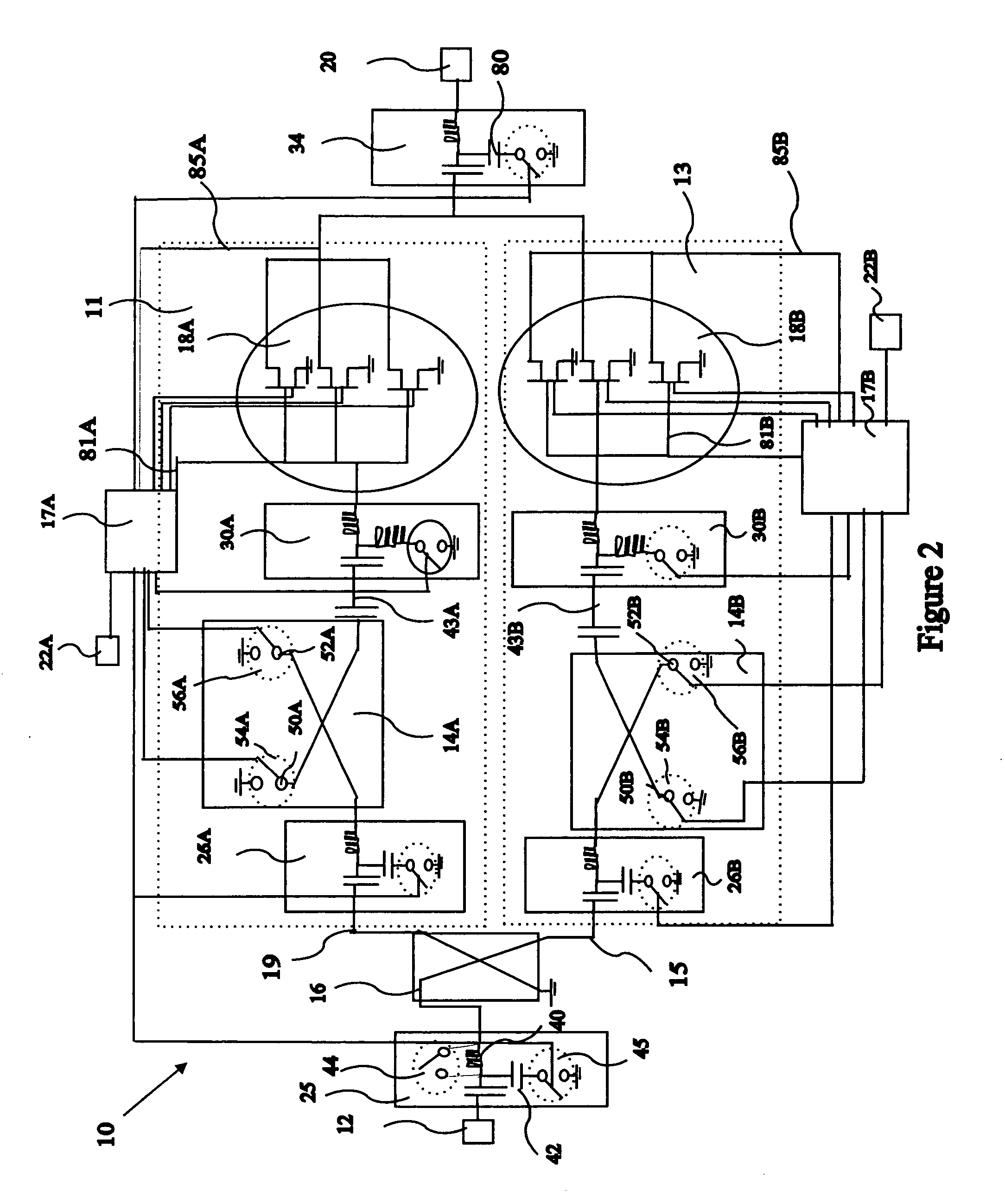
[0030] Referring particularly to FIG. 1, a block diagram of an electronically programmable multimode circuit 10 of the present invention is shown, which electronically programmable multimode circuit 10 may be programmed or re-programmed for at least one mode to perform various operations on a signal. Further, electronically programmable multimode circuit 10 includes a first path 11 and a second path 13. For purposes of describing the present invention, said electronically programmable multimode circuit 10 is described for transmitter and receiver applications. Further, it shall be noted that the present invention may be used for applications other than transmitter and receiver applications.

[0031] The electronically programmable multimode circuit 10 comprises a first port 12, a second port 20, electrodes 22A, 22B, control circuits 17A, 17B, a phase shift coupler 16, a first phase shift device 14A, a second phase shift device 14B, a first functional block 18A, and a second functional...


PUM


Abstract

An electronically programmable multimode circuit is described. More particularly, the present invention is an electronically programmable multimode circuit that includes a first path and a second path wherein a mode and a signal directional flow direction is controlled through the selective biasing of the first path and the second path. A multimode circuit is produced that contains modes such as a phase shifter mode, an IQ modulation mode, an amplifier mode, a mixer mode, and a multiplier mode.

Description

FIELD OF THE INVENTION [0001] The present invention relates to an electronically programmable, multimode circuit for electronic systems. More particularly, the present invention relates to an electronically programmable, multimode Monolithic Microwave Integrated Circuit (MMIC) that allows a user to electronically program and to reprogram the electronic hardware components so that the same multimode circuit may be utilized for multiple receive and transmit applications. For instance, the multimode circuit may be programmed for at least one mode selected from a group consisting of a phase shifter mode, an In-Phase and Quadrature (IQ) modulator mode, an amplifier mode, an attenuator mode, a multiplier mode, and a mixer mode. Multiple electronically programmable, multimode circuits may be cascaded to achieve a user desired electronic system functionality. DESCRIPTION OF THE PRIOR ART [0002] Electronic systems require electronic hardware to perform processing on an electronic signal, whi...

Claims


Application Information

Patent Timeline
12 May 2005
Publication
US20050099222A1
IPC
H03C3/40; H03F1/02; H03F3/21; H03F3/72
CPC
H03C3/40; H03F1/0277; H03F2200/372; H03F3/72; H03F3/211
Inventors
YANG, JEFFREY MING-JER; NISHIMOTO, MATT