Aircraft electrical system operating method

a technology of electrical system and operating method, which is applied in the direction of motor/generator/converter stopper, dynamo-electric converter control, instruments, etc., can solve the problems of engine shutdown, undemanded power drop, engine thrust control loss, etc., and achieve the effect of preventing fuel from leaking into the oil system

Active Publication Date: 2016-06-30
ROLLS ROYCE PLC
View PDF0 Cites 12 Cited by
  • Summary
  • Abstract
  • Description
  • Claims
  • Application Information

AI Technical Summary

Benefits of technology

[0018]Alternatively, or in addition, the normal condition may be met where the respective phase fault detection is found to have been erroneous. For example, the method may comprise detecting that the fault occurred on a further electrical component, such as a DC link/ring main. Where the fault is found to be on a further electrical component, the method may comprise isolating the further faulty component, and subsequently operating the electrical machine in the normal condition. Advantageously, the method allows the electrical machine to be operated above the nominal power rating for a period of time while the fault is fully diagnosed. If the fault is found to be caused to a further electrical component, i.e. by a component other than one of

Problems solved by technology

In the case of an MEE, where the engine accessory is required for continued operation of the engine, such as where the engine accessory comprises the fuel or oil pump, a fault within the electrical system may result in an undemanded drop in power and consequently a loss of thrust control, or possibly an engine shutdown.
Consequently, where essential engine accessory systems are electrically powered, suc

Method used


Image

  • Aircraft electrical system operating method
  • Aircraft electrical system operating method
  • Aircraft electrical system operating method

Examples


Embodiment Construction

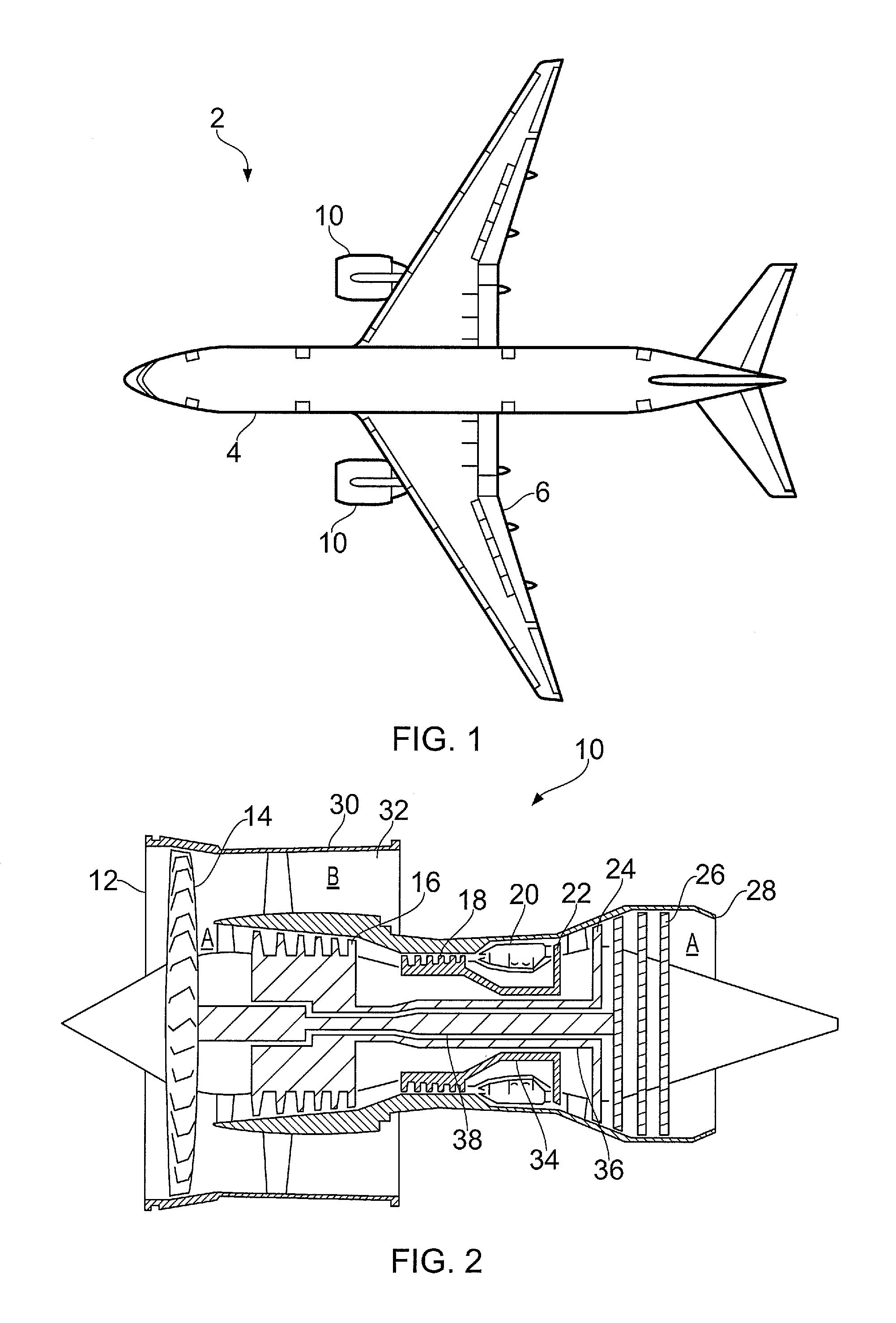
[0026]FIG. 1 shows a passenger aircraft 2. The aircraft 2 is of conventional construction, having a fuselage 4, wings 6, and a pair of wing mounted engines 10.

[0027]FIG. 2 shows a cross sectional schematic view of one of the engines 10. The engine 10 comprises an air intake 12 and a propulsive fan 14 that generates two airflows A and

[0028]B. The gas turbine engine 10 comprises, in axial flow A, an intermediate pressure compressor 16, a high pressure compressor 18, a combustor 20, a high pressure turbine 22, an intermediate pressure turbine 24, a low pressure turbine 26 and an exhaust nozzle 28. The high pressure turbine 22 is mechanically coupled to the high pressure compressor 18 by a high pressure shaft 34, the intermediate pressure turbine 24 is mechanically coupled to the intermediate pressure compressor 16 by an intermediate pressure shaft 36, and the low pressure turbine 26 is mechanically coupled to the fan 14 by a low pressure shaft 38. A nacelle 30 surrounds the gas turbine...


PUM


Abstract

A method of controlling an aircraft electrical system (40). The electrical system (40) comprises an alternating current electrical machine (56, 58) comprising a plurality of phases, each phase having a power rating, the electrical machine (56, 58) being configured to operate on failure of one or more phases. The method comprises: determining a power requirement; sensing a fault of one or more phases of the electrical machine (56, 58), and controlling the electrical machine (56, 58) to operate in a fault condition, in which the remaining phases of the electrical machine (56, 58) provide the electrical power requirement; and providing an overrating signal to a flight computer (66) of the aircraft (2) where the power provided by each phase exceeds the power rating of the respective phase.

Description

FIELD OF THE INVENTION[0001]The present invention relates to an aircraft electrical system, and to a method of controlling an aircraft electrical system to provide fault tolerant operation.BACKGROUND TO THE INVENTION[0002]Aircraft such as passenger aircraft comprise a number of powered systems, such as control surface actuators, passenger air systems and avionics. In traditional aircraft, some of these systems are electrically powered, while others are pneumatically or hydraulically powered. Aircraft engines, such as gas turbine engines, also comprise a number of powered accessory systems, such as fuel and oil pumps, which are powered by the engine itself. In recent years, there has been a move to provide electrically powered systems for aircraft and aircraft engine accessory systems to replace some or all of the pneumatic or hydraulic systems in order to save weight or reduce fuel burn, or a combination of the two. Aircraft having more electrical systems compared to traditional air...

Claims


Application Information

Patent Timeline
IPC IPC(8): B64D41/00H02P29/028B64D45/00
CPCB64D41/00B64D2221/00H02P29/028B64D45/00H02P29/0243H02P25/22H02P29/032B65D41/00
Inventor EDWARDS, HUW LLEWELLYNVYAS, PARAG
Owner ROLLS ROYCE PLC
Why Eureka
Try Eureka