Emergency device for relighting a windmilling turbojet

a technology of emergency device and windmilling, which is applied in the ignition of turbine/propulsion engine, engine starter, machine/engine, etc., can solve the problems of increasing the difficulty of relighting the combustion chamber, increasing the seriousness of the consequences in the event of engine shutting down, and reducing the speed at which the compressor rotates when windmilling, etc., to achieve continuous operation, reduce the effect of drawbacks, and simple, fast and reliable us

Inactive Publication Date: 2004-01-06
SN DETUDE & DE CONSTR DE MOTEURS DAVIATION S N E C M A
View PDF12 Cites 65 Cited by
  • Summary
  • Abstract
  • Description
  • Claims
  • Application Information

AI Technical Summary

Benefits of technology

The present invention thus seeks to mitigate such drawbacks by proposing an emergency device for relighting a windmilling turbojet, which device is continuously operational and simple, fast, and reliable to use.
To this end, the invention provides an emergency device for relighting a windmilling turbojet, the jet comprising a fan driven by a low-pressure turbine via a first shaft and a compressor driven by a high-pressure turbine via a second shaft disposed coaxially around the first shaft, said device comprising a differential interconnecting said first and second shafts while compensating for their different speeds of rotation in normal operation or the turbojet, and a braking system connected to the differential so as to enable it to be slowed down or blocked when the turbojet shuts down, thereby enabling the first shaft to entrain the second shaft so that it reaches a speed that favors relighting of the turbojet.

Problems solved by technology

The increase in the compression ratio and the inertia of the high-pressure compressor in such an engine has also led to the speed at which the compressor rotates when windmilling decreasing for given flight conditions, and this has had the consequence of increasing the difficulty of relighting the combustion chamber in the event of a shutdown.
Furthermore, the use of twin jets for long flights over oceans increases the seriousness of the consequences in the event of an engine shutting down in flight.
Furthermore, for various reasons, a twin jet can also be the subject of multiple shutdowns, something which happens extremely rarely, but is still possible.
However, in the event of multiple extinctions for a common mode cause, the starter has no external power if the auxiliary power unit has stopped or been shut down, so it cannot be used, and the engine must be relighted while it is windmilling.
The power available from the batteries of twin jets is limited, so emergency electrical systems cannot restart the engine.
The power generated by the emergency air turbine is low (about 5 kilowatts (kW)) and the mass penalty associated with such a turbine is very large (about 100 kilograms (kg)), and it requires regular inspections.
The high-pressure compressor receives only a small fraction of this relative wind, and therefore does not always rotate at a speed that is fast enough to allow the engine to be relighted without external assistance.
Nevertheless, each of those relighting systems presents the major drawback of constituting an assembly that is complicated and bulky.
However, that relighting device is not very reliable.
It is very difficult to calibrate, so there is always a risk of it not disengaging at the right moment.

Method used


Image

  • Emergency device for relighting a windmilling turbojet
  • Emergency device for relighting a windmilling turbojet
  • Emergency device for relighting a windmilling turbojet

Examples


first embodiment

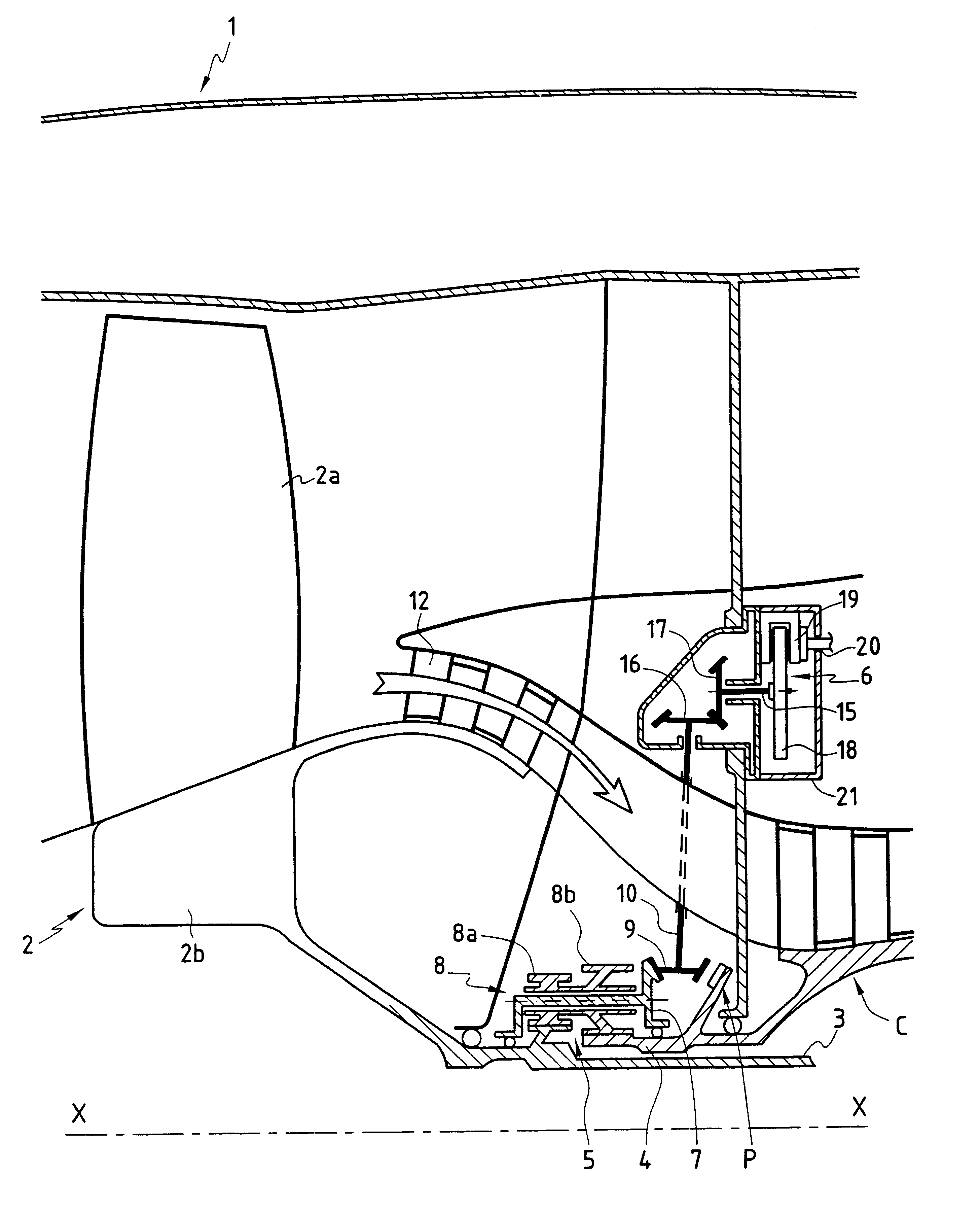
In order to assist or replace the starter in flight, the turbojet includes an emergency relighting device. In a first embodiment, this device comprises a differential 5 and a braking system 6. The differential 5 serves to interconnect the low- and high-pressure shafts 3 and 4 and serves to compensate for the speed differences between the high-pressure body and the low-pressure body during normal operation of the turbojet.

It is known that the low- and high-pressure bodies rotate at different speeds. For example, for a conventional turbojet having a large bypass ratio, the high-pressure body has an N2 speed of rotation of about 10,000 revolutions per minute (rpm) to 12,000 rpm, and the low-pressure body runs at an N1 speed of about 2,000 rpm to 3,000 rpm. With these values, the ratio between these speeds lies in the range about 3 to 6.

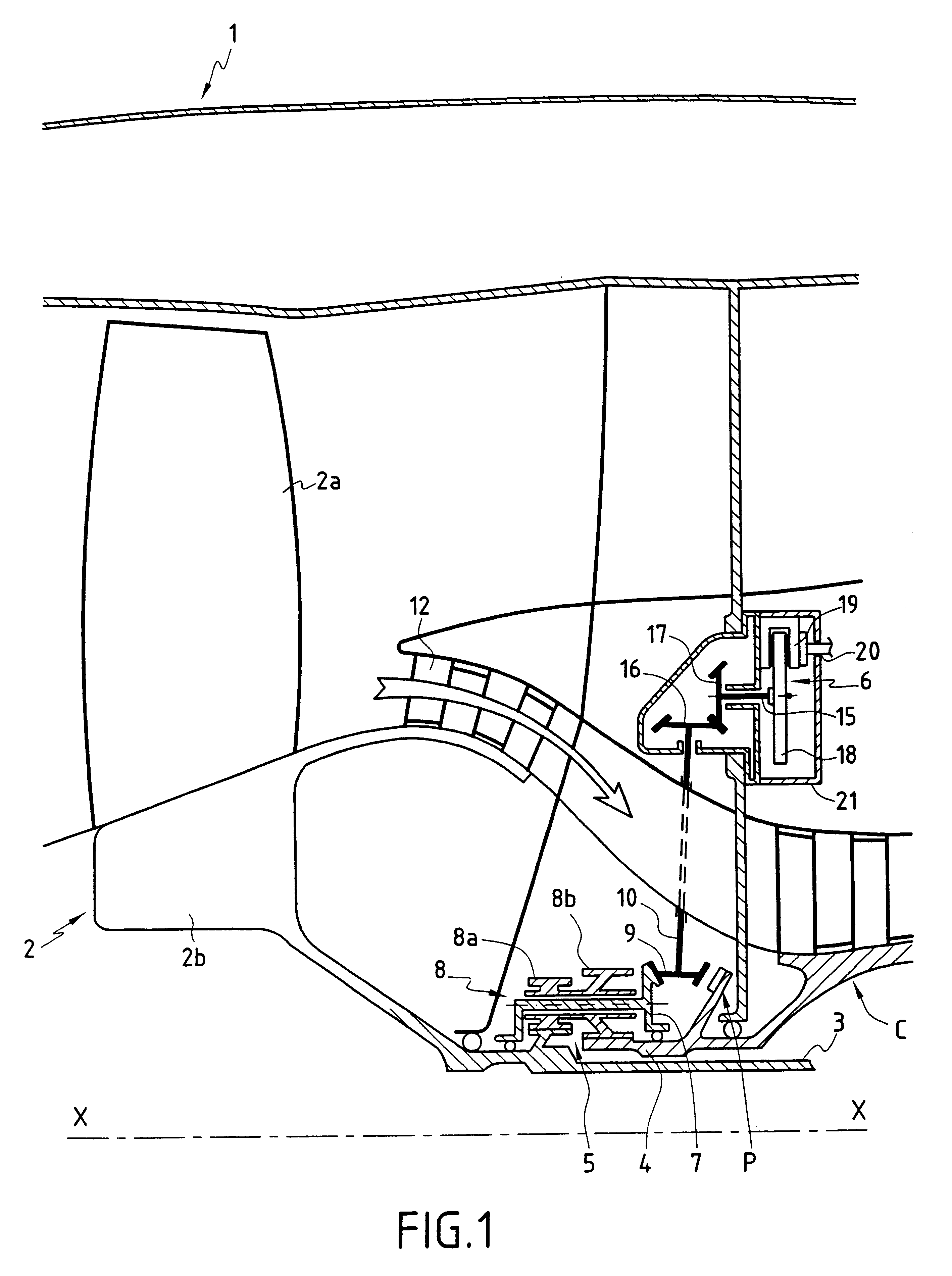
In order to compensate for these speed differences, the differential 5 in this first embodiment essentially comprises (cf. FIGS. 2 and 3):

at least one p...

second embodiment

In the invention show in FIG. 5, the differential 5' of the emergency relighting device is placed at a braking system 61 outside an intermediate casing 22. The advantage of this configuration is that it facilitates maintenance of the emergency relighting device (e.g. changing the differential), since it is thus made easily accessible.

In the example shown in FIG. 5, it can be seen that the emergency relighting device is made up in particular of two bevel gears 23, 24, which mesh respectively with the first and second shafts 3 and 4 and which are connected to the differential 5' via two respective drive shafts 25 and 26 that are concentric. The differential 5' is a conventional configuration of gears and is therefore not described in detail. The two drive shafts are not necessarily concentric; they could be parallel.

It should also be observed that the braking system 6' is identical to that used in the first embodiment, i.e. it is advantageously constituted by a disk brake.

Naturally, t...


PUM


Abstract

An emergency device for relighting a windmilling turbojet, the jet comprising a fan driven by a low-pressure turbine via a first shaft and a compressor driven by a high-pressure turbine via a second shaft disposed coaxially around the first shaft, a differential interconnecting said first and second shafts while compensating for their different speeds of rotation in normal operation or the turbojet, and a braking system connected to the differential so as to enable it to be slowed down or blocked when the turbojet shuts down, thereby enabling the first shaft to entrain the second shaft so that it reaches a speed that favors relighting of the turbojet.

Description

The present invention relates to an emergency device for relighting an airplane turbojet that is windmilling, and more particularly when the jet has suffered an in-flight shutdown.In the past, long-distance airliners have generally been fitted with four engines. Those airplanes have subsequently been replaced by airplanes propelled by only three engines. This trend towards reducing the number of engines on that type of airplane, together with the trend towards increasing the capacity of airplanes so as to reduce operating costs, has led to large capacity twinjet airplanes known as "large twins" being designed.The engines fitted to that type of airplane have been developed so as to provide very high thrust with large bypass ratios. The increase in the compression ratio and the inertia of the high-pressure compressor in such an engine has also led to the speed at which the compressor rotates when windmilling decreasing for given flight conditions, and this has had the consequence of i...

Claims


Application Information

Patent Timeline
Patent Type & Authority Patents(United States)
IPC IPC(8): F02C3/00F02C3/113F02C7/26F02C7/262F02C7/264F02C7/275F02K3/06
CPCF02C3/113F02C7/262F02K3/06Y02T50/671F05D2220/50Y02T50/60
Inventor FRANCHET, MICHELHEBRAUD, GUY
Owner SN DETUDE & DE CONSTR DE MOTEURS DAVIATION S N E C M A
Why Eureka
Try Eureka