High pressure liquid jet cutting system and method for forming polymer pellets

a cutting system and liquid jet technology, applied in the field of high pressure liquid jet cutting system and method for forming polymer pellets, can solve the problems of cutting blade wear and die face wear, and achieve the effect of not requiring unnecessary down tim

Inactive Publication Date: 2005-04-14
GALA INDUSTRIES INC
View PDF21 Cites 65 Cited by
  • Summary
  • Abstract
  • Description
  • Claims
  • Application Information

AI Technical Summary

Benefits of technology

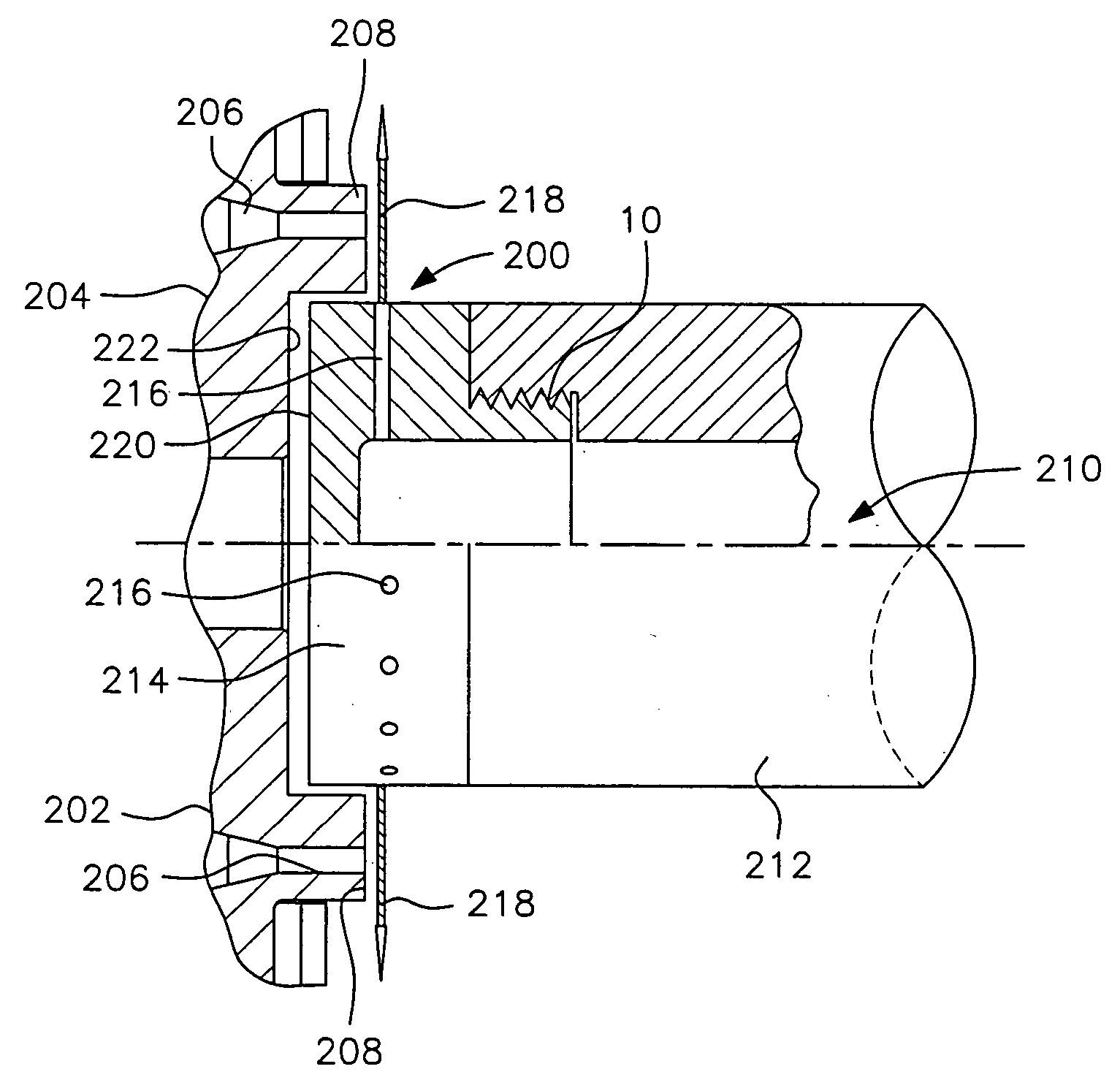
[0025] Accordingly, it is an object of the present invention to provide a high pressure water stream cutter system and method for thermoplastic pellets for underwater, hot face and strand applications in which the blades and other mechanical cutting implements can be eliminated.
[0026] Another object of the present invention is to provide a high pressure water stream cutter system and method in accordance with the previous object which can operate continuously without unnecessary down time for replacement of worn blades or other worn cutting implements.

Problems solved by technology

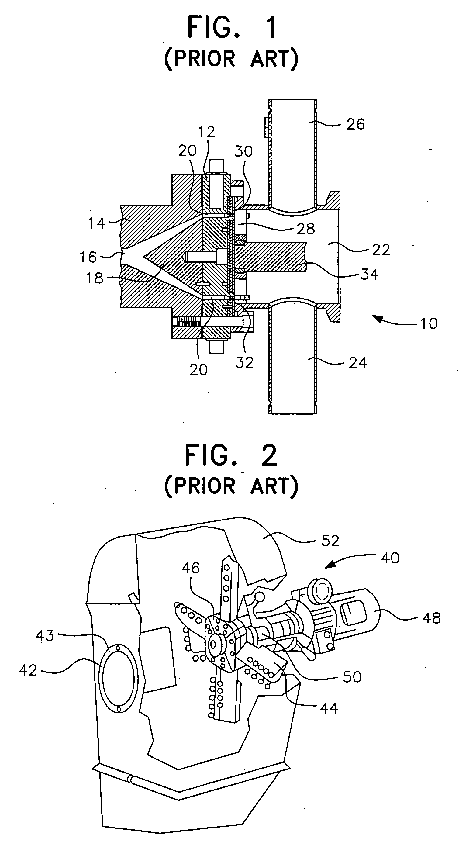
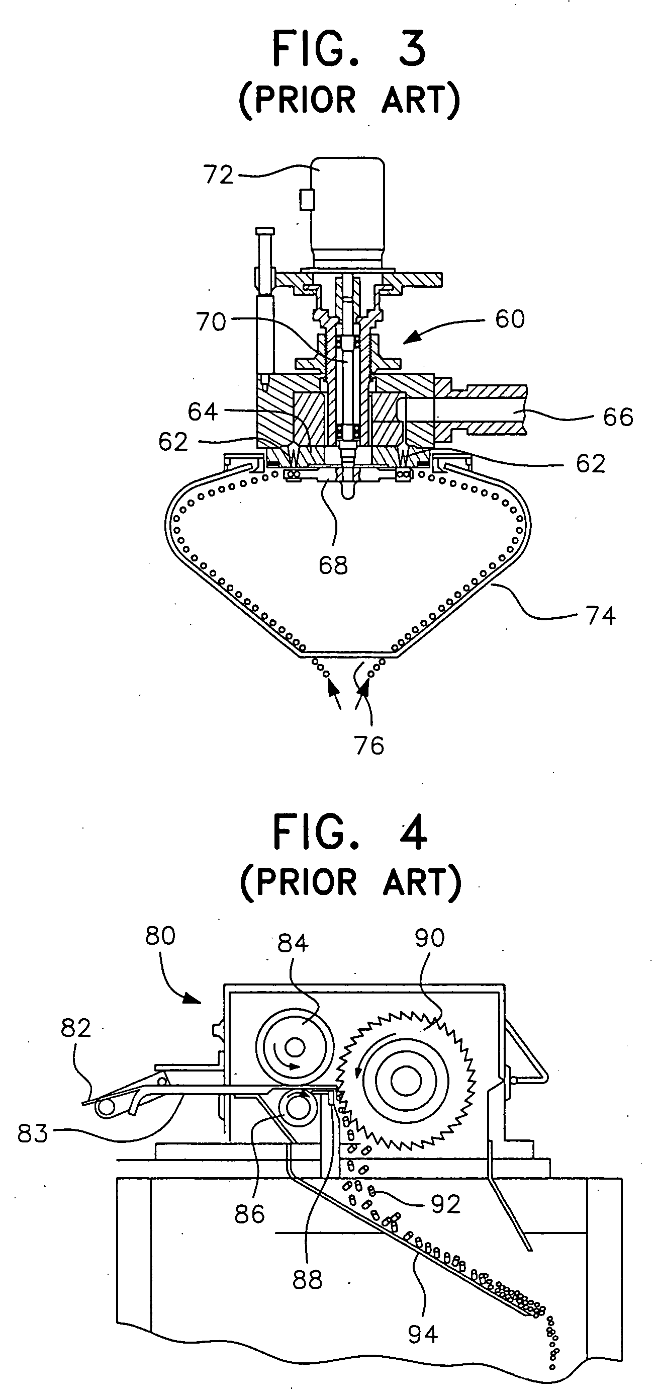
These cutting blades and the die face are subject to the wear as the blades engage the surface of the die face during cutting of the pellets.

Method used


Image

  • High pressure liquid jet cutting system and method for forming polymer pellets
  • High pressure liquid jet cutting system and method for forming polymer pellets
  • High pressure liquid jet cutting system and method for forming polymer pellets

Examples


example 1

[0092] Ethylene vinyl acetate (EVA) copolymer was pelletized using the equipment described above for a period of about 2 hours under the following operating conditions:

Cutter Speed (RPM)2000Pelletizer Motor Load (amps)3.8Process Water Temperature (° F.)102Process Water Flow Rate (GPM)80Cutting Water Temperature (° F.)85Cutting Water Flow (GPM / nozzle)3Cutting Water Pressure (PSI @ pump)2500Polymer Melt Temperature (° F.)445Die Hole Size (inches).078Number of Die Holes18Polymer Production Rate (lb / hr)100

[0093] The EVA polymer pellets range in size from about 0.070 inch to 0.090 inch and had a generally spherical shape.

example 2

[0094] Polypropylene polymer was pelletized using the equipment described above for a period of about 1 hour under the following operating conditions:

Cutter Speed (RPM)2500Pelletizer Motor Load (amps)3.4Process Water Temperature (° F.)155Process Water Flow Rate (GPM)80Cutting Water Temperature (° F.)155Cutting Water Flow (GPM / nozzle)3Cutting Water Pressure (PSI @ pump)2500Polymer Melt Temperature (° F.)425Die Hole Size (inches).093Number of Die Holes6Polymer Production Rate (lb / hr)60

[0095] The polypropylene polymer pellets ranged in size from about 0.080 inch to 0.100 inch and had a generally spherical shape.

example 3

[0096] EVA was again pelletized using the equipment described above for a period of about 2 hours under the following operating conditions:

Cutter Speed (RPM)2000Pelletizer Motor Load (amps)4.7Process Water Temperature (° F.)91Process Water Flow Rate (GPM)80Cutting Water Temperature (° F.)91Cutting Water Flow (GPM / nozzle)3Cutting Water Pressure (PSI @ pump)2400Polymer Melt Temperature (° F.)440Die Hole Size (inches).093Number of Die Holes1Polymer Production Rate (lb / hr)10.5

[0097] The EVA pellets ranged in size from about 0.080 inch to 0.100 inch and had a generally spherical shape.


PUM

PropertyMeasurementUnit
approach angleaaaaaaaaaa
spread angleaaaaaaaaaa

Abstract

A system and method for pelletizing extruded materials, such as thermoplastic polymers in various pelletizing applications, including underwater, hot face, and strand pelletizing applications, utilizes a high pressure liquid delivered to one or more nozzles which direct a high pressure liquid jet cutting stream at the extruded polymer strand to cut the strand into pellets. The system and method are particularly applicable to underwater pelletizers utilizing water or water-based solutions. In a preferred underwater pelletizing embodiment, a plurality of nozzles are mounted on a rotating nozzle hub which is fed high pressure water through sealed hollow pelletizer and hollow motor shafts. The high pressure water jet cutting streams exiting the rotating nozzles are preferably in the form of a flat V-shaped spray with a spread angle of about 15° to about 45° and an approach angle between 0° and 60°, depending upon the pelletizing application.

Description

RELATED APPLICATION [0001] This application is entitled to and hereby claims the priority of co-pending U.S. Provisional Application Ser. No. 60 / 494,797, filed Aug. 14, 2003.FIELD OF INVENTION [0002] The present invention generally relates to a high pressure liquid jet stream system and method utilized as a cutting medium for forming pellets from extruded materials, such as molten thermoplastic polymers, that eliminate the need for cutter blades and expensive die assemblies. More specifically, the present invention relates to high pressure water and water-based liquid jet streams for cutting extruded materials various pelletizing applications, including in underwater, hot face and strand pelletizing applications. DESCRIPTION OF PRIOR ART [0003] Conventional cutting systems for pelletization of molten polymers and other extruded materials have been mechanical in nature and include, for example, a rotatable cutter hub and blades associated with a die plate. Conventional cutter hub and...

Claims


Application Information

Patent Timeline
Patent Type & Authority Applications(United States)
IPC IPC(8): B26F3/00B29B9/06
CPCB26F3/004B29B9/065B29B9/06B29C48/0022B29C48/05
Inventor BRYAN, DAVID E.FALLS, TIMOTHY N.
Owner GALA INDUSTRIES INC
Why Eureka
Try Eureka