Electron emission device and driving method thereof

Inactive Publication Date: 2005-05-12
SAMSUNG SDI CO LTD
View PDF1 Cites 20 Cited by
  • Summary
  • Abstract
  • Description
  • Claims
  • Application Information

AI Technical Summary

Benefits of technology

[0016] In exemplary embodiments according to the present invention, is provided an electron emission device panel driver for c

Problems solved by technology

Hence, it is difficult to expect a white visual characteristic in moving pictures.
Also, in the case of the full white mode, the amount of the current

Method used


Image

  • Electron emission device and driving method thereof
  • Electron emission device and driving method thereof
  • Electron emission device and driving method thereof

Examples


Example

[0033] In the following detailed description, only certain exemplary embodiments of the present invention are shown and described, simply by way of illustration. As those skilled in the art would realize, the described embodiments may be modified in various different ways, all without departing from the spirit or scope of the present invention. Accordingly, the drawings and description are to be regarded as illustrative in nature, and not restrictive. To clarify the present invention, parts which are not described in the specification may have been omitted.

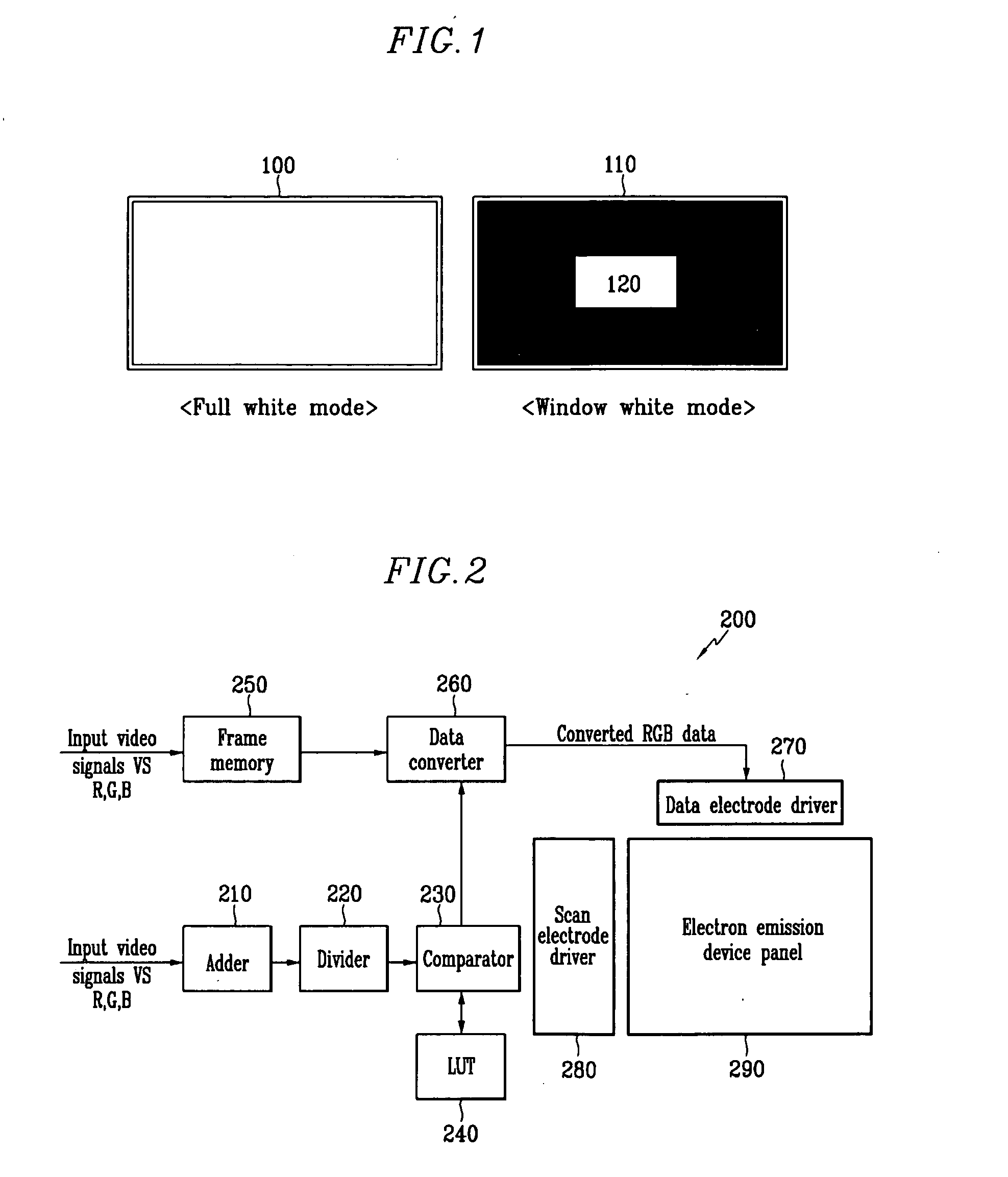
[0034]FIG. 1 shows a full white mode 100 wherein an overall brightness level is high, and a window white mode 110 wherein a part of the screen is white. It can be seen in FIG. 1 that a white area 120 of the screen is surrounded by darker areas.

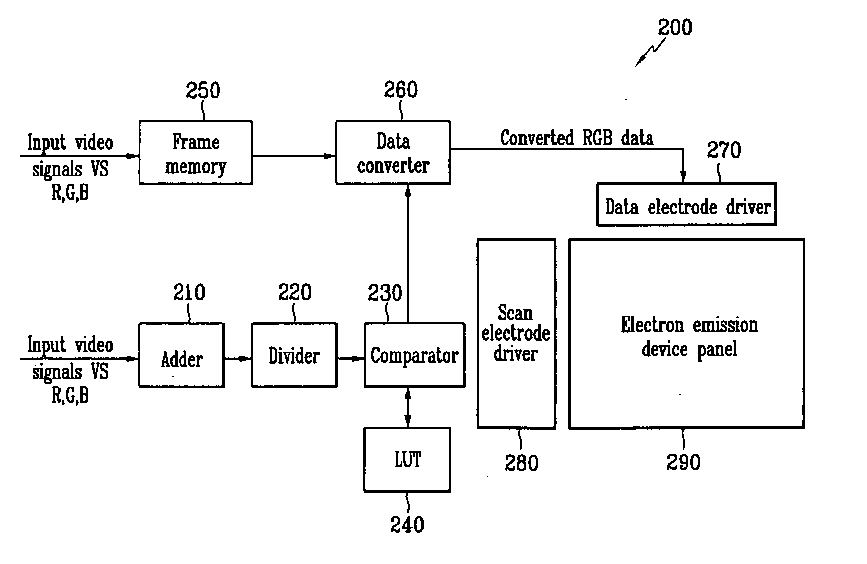
[0035]FIG. 2 shows a simplified view of an EED 200 according to a first exemplary embodiment of the present invention.

[0036] The EED 200 converts data for each frame according to the brig...


PUM


Abstract

An electron emission device for controlling brightness by converting a brightness level of input video signals. The electron emission device calculates brightness levels of video data which indicate a brightness degree for each of the images corresponding to the video signals, compares the brightness levels with a reference brightness level stored in a lookup table, calculates a conversion index of the input video signals, converts the video data stored in a memory according to the calculated conversion index, and displays the images based on the converted video data.

Description

CROSS REFERENCE TO RELATED APPLICATION [0001] This application claims priority to and the benefit of Korea Patent Application No. 10-2003-0068361 filed on Oct. 1, 2003 in the Korean Intellectual Property Office, the entire content of which is incorporated herein by reference. BACKGROUND OF THE INVENTION [0002] (a) Field of the Invention [0003] The present invention relates to an electron emission device. More specifically, the present invention relates to an electron emission device for varying brightness levels of input video signals to control the brightness of displayed images. [0004] (b) Description of the Related Art [0005] In general, a flat panel display (FPD) is a display device in which a wall is provided between two substrates to manufacture an airtight device, and appropriate elements are arranged in the airtight device to display desired images. The importance of the FPD has been emphasized following the development of multimedia technologies. In response to this trend, ...

Claims


Application Information

Patent Timeline
IPC IPC(8): G09G3/22G09G3/20G09G5/10H04N5/57
CPCG09G3/2014G09G2320/0271G09G2320/0233G09G3/22
Inventor KANG, MUN-SEOKLEE, CHUN-GYOO
Owner SAMSUNG SDI CO LTD
Why Eureka
Try Eureka