Led drive circuit

A circuit and LED driving technology, applied in the direction of circuit, circuit layout, lamp circuit layout, etc., can solve the problems of unable to control the LED driving current normally, unable to operate normally, unable to control the brightness of LED79 constantly, etc.

Inactive Publication Date: 2008-07-30
SEIKO INSTR INC
View PDF1 Cites 9 Cited by
  • Summary
  • Abstract
  • Description
  • Claims
  • Application Information

AI Technical Summary

Problems solved by technology

[0011] In the conventional step-up switching regulator type LED drive circuit, the step-up operation is performed when VinVout due to the difference in Vf of the LED79, it cannot operate normally.
Therefore, the LED drive circuit cannot keep the output voltage Vout constant, cannot normally control the LED drive current, and thus cannot constantly control the brightness of the LED79

Method used


Image

  • Led drive circuit
  • Led drive circuit
  • Led drive circuit

Examples


no. 1 approach

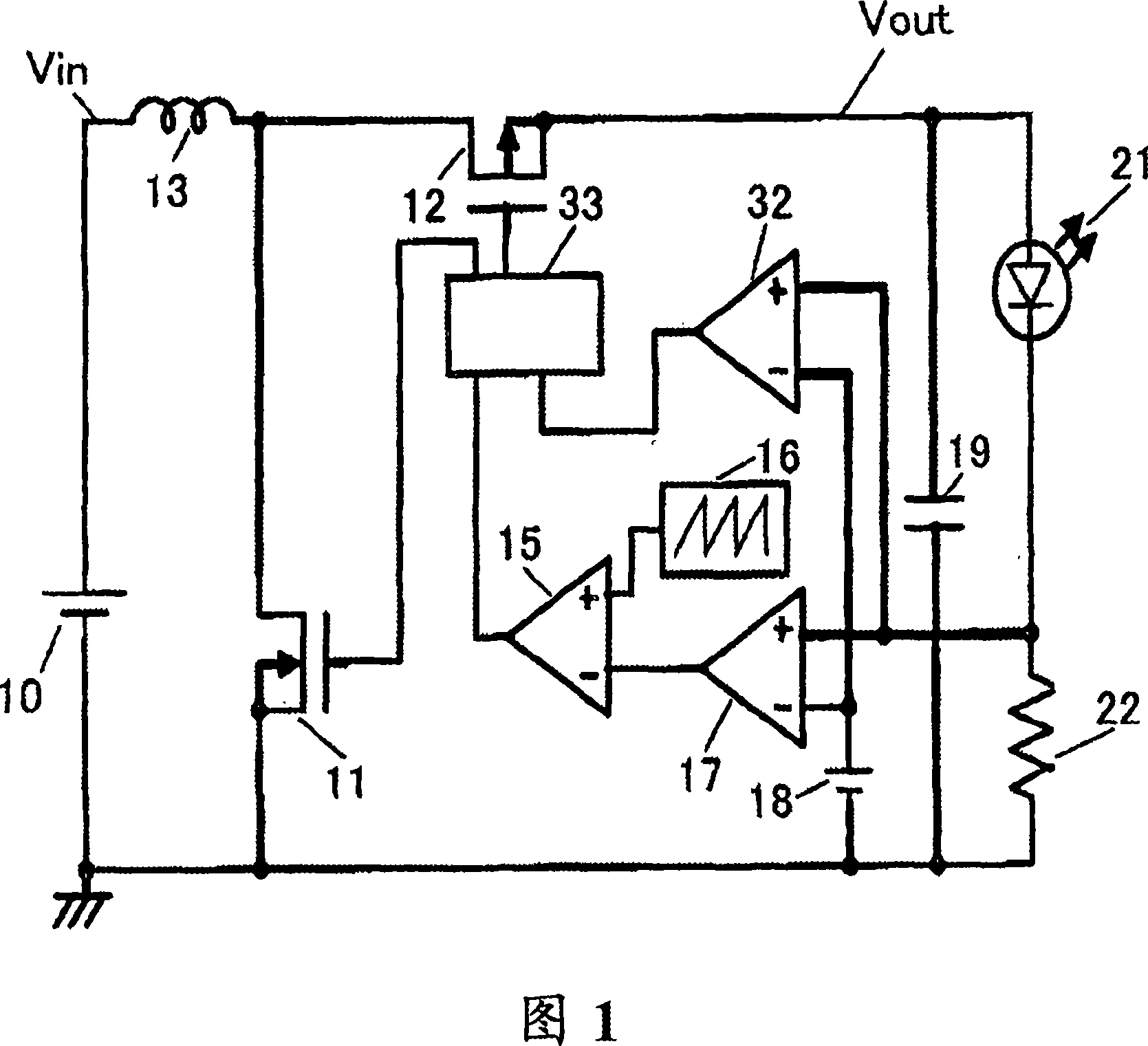
[0036] First, the structure of the LED drive circuit of the first embodiment will be described. FIG. 1 is a diagram showing an LED driving circuit according to a first embodiment.

[0037] The LED drive circuit includes an input power source 10 and a DCDC converter. The DCDC converter includes an NMOS transistor 11 , a PMOS transistor 12 , an inductor 13 , a comparator 15 , an oscillation circuit 16 , an error amplifier 17 , a reference voltage circuit 18 , a capacitor 19 , an error amplifier 32 , and a control circuit 33 . The load circuit includes LED 21 and resistor 22 .

[0038] The DCDC converter is connected to the input power source 10 and connected to the load circuit.

[0039] One end of the inductor 13 is connected to the input terminal, and the other end is connected to the drains of the transistor 11 and the transistor 12 . The source of transistor 11 is grounded. The source of the transistor 12 is connected to the output terminal. One end of the capacitor 19 ...

no. 2 approach

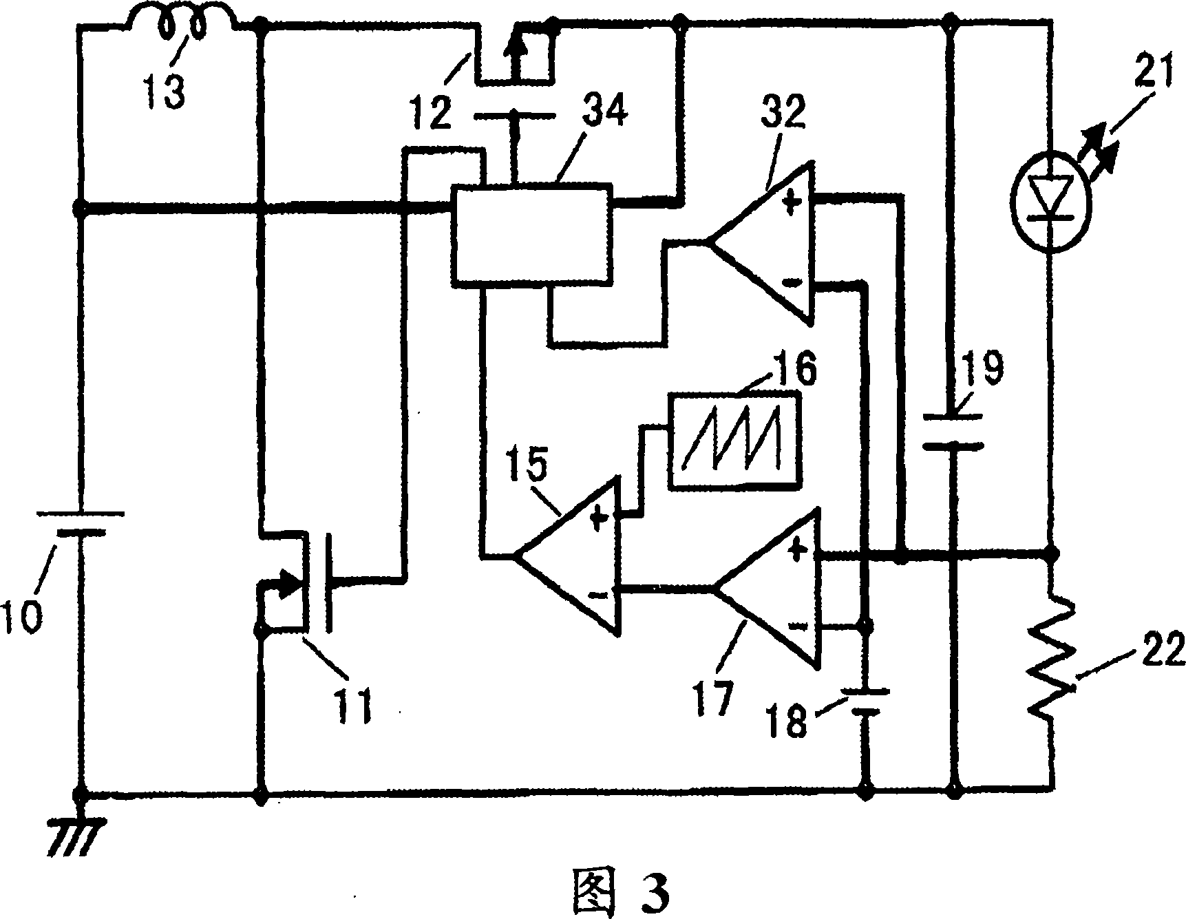
[0056] Next, the structure of the LED drive circuit of the second embodiment will be described. Fig. 3 is a diagram showing an LED driving circuit according to a second embodiment.

[0057] The LED drive circuit of the second embodiment differs from the LED drive circuit of the first embodiment in that the control circuit 33 is changed to a control circuit 34 . In addition, the control circuit 34 is connected to an input terminal (input voltage Vin) and an output terminal (output voltage Vout).

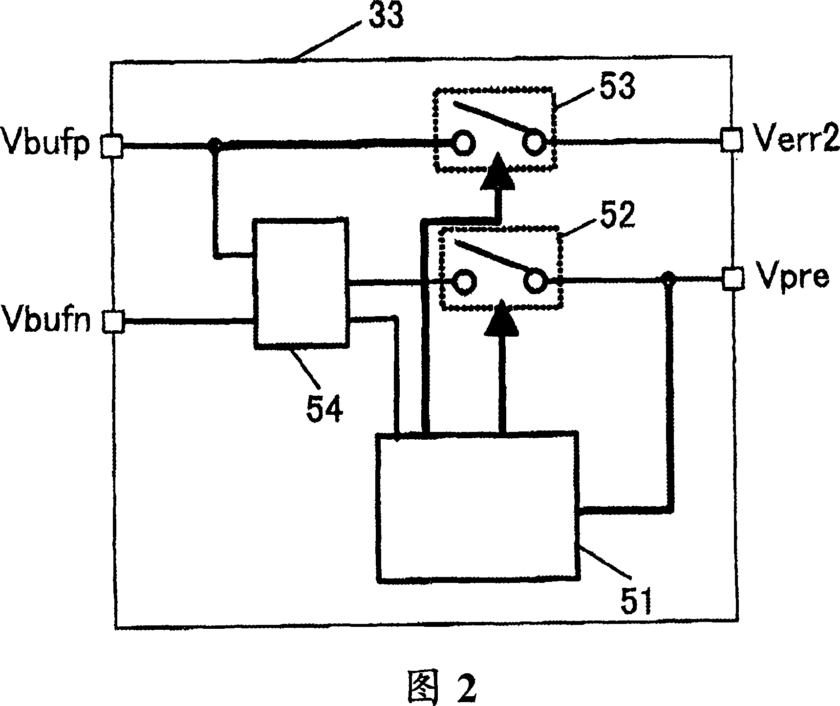
[0058] Next, the configuration of the control circuit 34 of the second embodiment will be described. Fig. 4 is a control circuit diagram showing a second embodiment.

[0059] The control circuit 34 of the second embodiment differs from the control circuit 33 of the first embodiment in that the 100% duty ratio detection circuit 51 is replaced with a voltage detection circuit 55 . In addition, this voltage detection circuit 55 is connected to an input terminal (input voltage Vin) and...


PUM


Abstract

With the LED driving circuit of the present invention, even if the input voltage is higher than the output voltage, the brightness of the LED can be controlled to be constant. If the input voltage Vin is higher than the output voltage Vout due to the difference in the threshold voltage Vf of the LED (21), and the LED drive circuit cannot perform the step-up operation, the operation of the LED drive circuit is switched from a step-up switching regulator to a voltage regulator. action, therefore, the LED drive circuit can operate normally.

Description

technical field [0001] The invention relates to a light emitting diode (LED) driving circuit for driving a light emitting diode. Background technique [0002] Currently, liquid crystal displays are widely used in portable devices such as mobile phones. In this liquid crystal display, light-emitting diodes are widely used as light-emitting elements for backlights. [0003] By applying a voltage equal to or higher than the LED threshold voltage (Vf) between the positive terminal and the negative terminal, an LED drive current for driving the LED flows between the positive terminal and the negative terminal, thereby causing the LED to emit light. The brightness of the LED changes according to the current value of the LED driving current. [0004] Here, in order to improve the quality of the liquid crystal display, it is necessary to control the LED drive current to be constant, so that the brightness of the LED is constant. As a technique for controlling LED drive current, t...

Claims


Application Information

Patent Timeline
Patent Type & Authority Applications(China)
IPC IPC(8): H05B37/02G05F1/46F21V23/00F21Y101/02H01L33/00
CPCH05B45/38Y02B20/30
Inventor 增子裕之
Owner SEIKO INSTR INC
Why Eureka
Try Eureka