Method of searching for motion vector, method of generating frame interpolation image and display system

a frame interpolation image and motion vector technology, applied in the field of searching for motion vector, can solve problems such as unnatural movement, correlated blocks and uncorrelated blocks, and blur phenomena

Inactive Publication Date: 2005-05-12
KK TOSHIBA
View PDF1 Cites 53 Cited by
  • Summary
  • Abstract
  • Description
  • Claims
  • Application Information

AI Technical Summary

Benefits of technology

[0014]FIG. 3 shows an image output result and

Problems solved by technology

A problem of the hold type display unit is a blur phenomenon occurring in a motion video display.
Another problem of the hold type display unit is to occur unnatural movement when a motion video of few fra

Method used


Image

  • Method of searching for motion vector, method of generating frame interpolation image and display system
  • Method of searching for motion vector, method of generating frame interpolation image and display system
  • Method of searching for motion vector, method of generating frame interpolation image and display system

Examples


first embodiment

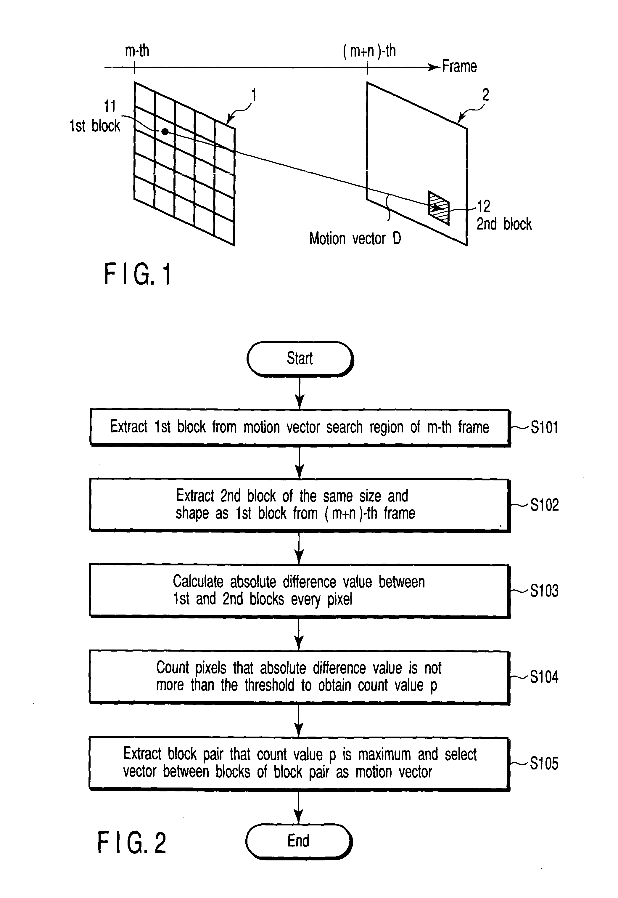
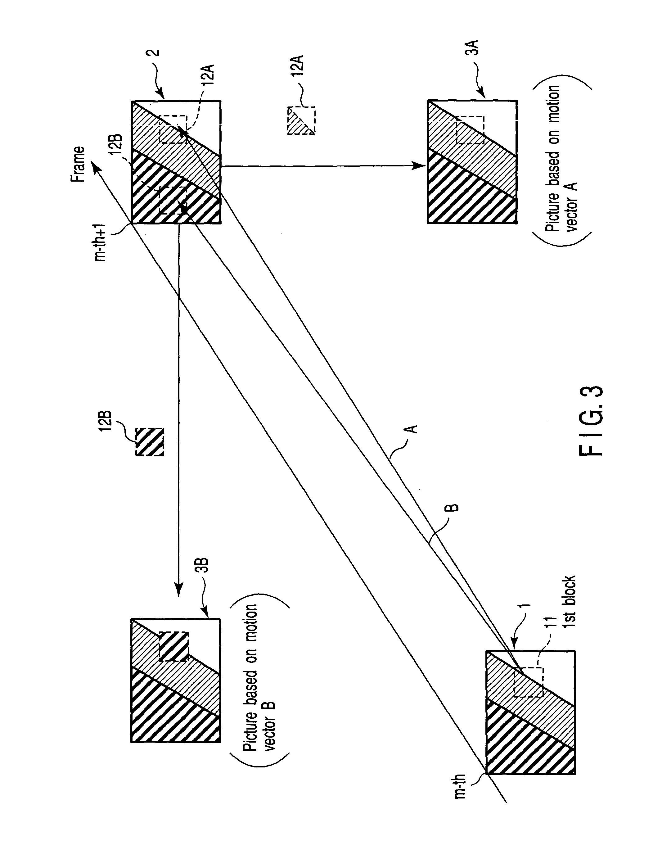
[0043] A procedure shown in FIG. 2 is used in the first embodiment of the present invention to detect a motion vector between the m-th frame (m is integer) 1 and (m+n)-th frame (n is an integer not less than 1) 2 of an original video as shown in FIG. 1. The procedure of the present embodiment is described in conjunction with FIGS. 1 and 2 hereinafter.

[0044] At first, the image data of the m-th frame 1 is divided into a plurality of first blocks 11, and the first blocks 11 are extracted sequentially (step S101).

[0045] The second block 12 of the same size and shape as the first block 11 extracted in step S101 is extracted from the image data of the (m+n)-th frame 2 (step S102).

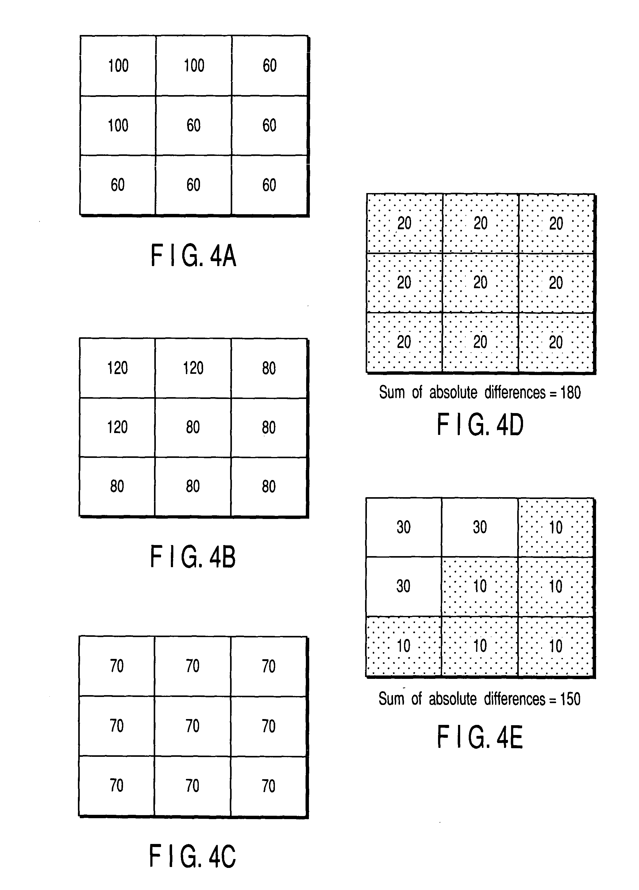
[0046] The absolute difference value of the corresponding pixels of the first block 11 extracted in step S101 and the second block 12 extracted in step S102 is computed every pixel (step S103). Therefore, the number of differential absolute values is equal to the number of pixels in a block.

[0047] Each absol...

second embodiment

[0061] As shown in FIG. 7, a motion vector from the m-th frame of an original picture (m is an integer) to the (m+n)-th frame (n is an integer not less than 1) is detected, and also a motion vector from the (m+n)-th frame to the m-th frame is detected. In the second embodiment of the present invention, such bidirectional motion vectors are detected according to a procedure shown in FIG. 8. The procedure of the present embodiment is described in conjunction with FIGS. 7 and 8 hereinafter. In FIG. 8, the process of steps S201 to S205 is similar to that of steps S101 to S105 of FIG. 2.

[0062] In other words, at first the image data of the m-th frame 1 is divided into a plurality of first blocks 11 to be extracted sequentially (step S101).

[0063] The second block 12 of the same size and shape as the first block 11 extracted in step S201 is extracted from the image data of the (m+n)-th frame 2 (step S202).

[0064] The first absolute difference values of opposite pixels of the first block ...

third embodiment

[0082] As shown in FIG. 10, in order to detect a motion vector F between the m-th frame (m is an integer) 1 of an original picture and the (m+n)-th frame (n is an integer not less than k+1, k is a real number) thereof, the (m+k)-th (k is a real number) frame 4 is supposed to be between the m-th frame 1 and the (m+n)-th frame 2. Assuming that third and fourth motion vectors extend to the m-th frame 1 and (m+n)-th frame 2, respectively, from the (m+k)-th frame 4.

[0083] The (m+k)-th frame 4 is an imagination frame which is supposed to be halfway between the m-th frame 1 and the (m+n)-th frame 2 as described above and does not exist in the original picture. It is a bunch of image data capable of newly forming based on the original picture. The process procedure of the present embodiment is described in conjunction with FIGS. 10 and 11 hereinafter.

[0084] At first, the image data of the (m+k)-th frame 4 is divided into a plurality of fifth blocks 15 to be extracted (step S301).

[0085] T...


PUM


Abstract

A motion vector detection method comprises extracting a first block including a plurality of pixels from a first frame of the image, detecting a second block from a plurality of blocks of a second frame of the image by block matching, the second block including the maximum number of pixels each indicating an absolute difference value not more than a first threshold with respect to each of the pixels of the first block, and computing a first motion vector between the first block and the second block.

Description

CROSS-REFERENCE TO RELATED APPLICATIONS [0001] This application is based upon and claims the benefit of priority from the prior Japanese Patent Application No. 2002-266642, filed Sep. 12, 2002, the entire contents of which are incorporated herein by reference. BACKGROUND OF THE INVENTION [0002] 1. Field of the Invention [0003] The present invention relates to a method of searching for a motion vector, a method of generating a frame interpolation image by motion compensation using the motion vector, and a display system. [0004] 2. Description of the Related Art [0005] Generally, there is two kinds of display units, one is an impulse type display unit that continues emitting light only by afterglow of a fluorescent substance after writing of an image, for example, CRT or field emission type display unit (FED), and the other is a hold type display unit that continues holding display of a previous frame till a new image is written, for example, Liquid Crystal Display (LCD) and Electro L...

Claims


Application Information

Patent Timeline
IPC IPC(8): G06T7/20H04N5/14H04N7/01H04N7/12H04N19/105H04N19/134H04N19/136H04N19/139H04N19/176H04N19/186H04N19/192H04N19/196H04N19/423H04N19/50H04N19/503H04N19/51H04N19/587H04N19/80H04N19/86
CPCG06T7/202H04N7/014H04N5/145G06T7/231H04N19/51
Inventor ITOH, GOHMISHIMA, NAOOKUMURA, HARUHIKO
Owner KK TOSHIBA
Why Eureka
Try Eureka