
Hinge structure for flat visual display device

a visual display device and hinge technology, applied in the direction of wing accessories, manufacturing tools, instruments, etc., can solve the problem that the rotational shaft inserted to the central shaft of the hinge should be cut, and achieve the effect of swinging

Inactive Publication Date: 2005-05-19
LG ELECTRONICS INC
View PDF17 Cites 25 Cited by
  • Summary
  • Abstract
  • Description
  • Claims
  • Application Information

AI Technical Summary

Benefits of technology

[0012] The present invention having the structure as disclosed above is capable of distributing frictional force uniformly over the more broad area upon rotation of the rotational shaft, thereby adjusting operation of the flat visual display device in a swift manner.
[0013] Also, the present invention is capable of controlling breaking force necessary for adjustment of the flat visual display device.

Problems solved by technology

But, the conventional hinge structures such as those proposed above have a problem that a rotational shaft inserted to a central shaft of the hinge should be cut by a predetermined flat panel.
Also, the conventional hinge structure was problematic in that in order for adjustment of breaking force of the hinge, the rotational shaft inserted to the fixing member and the rotational member should be tightened separately in its both ends by a plurality of nuts and washers, namely, external force should be applied via complicated route.

Method used


Image

  • Hinge structure for flat visual display device
  • Hinge structure for flat visual display device
  • Hinge structure for flat visual display device

Examples


Embodiment Construction

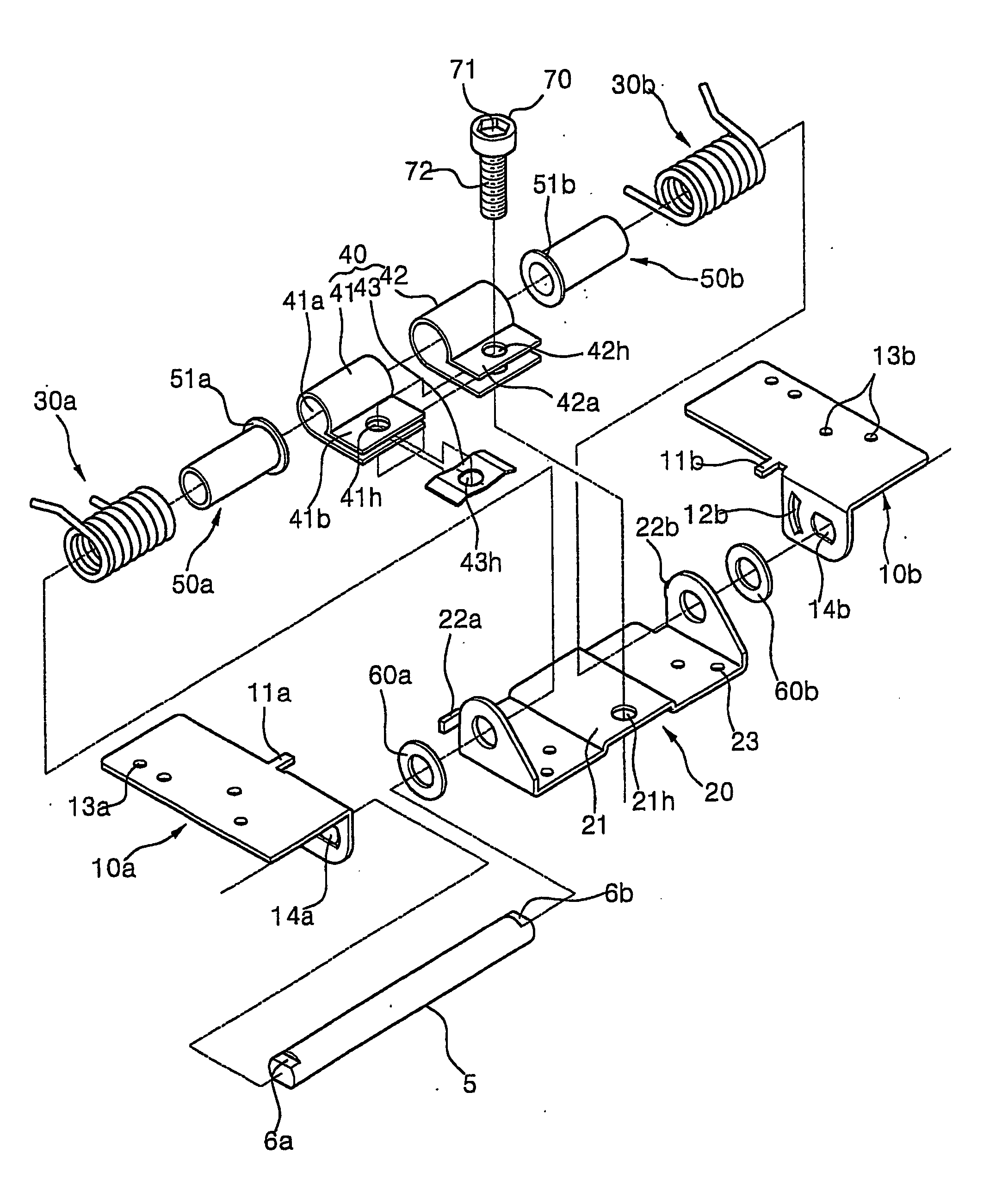
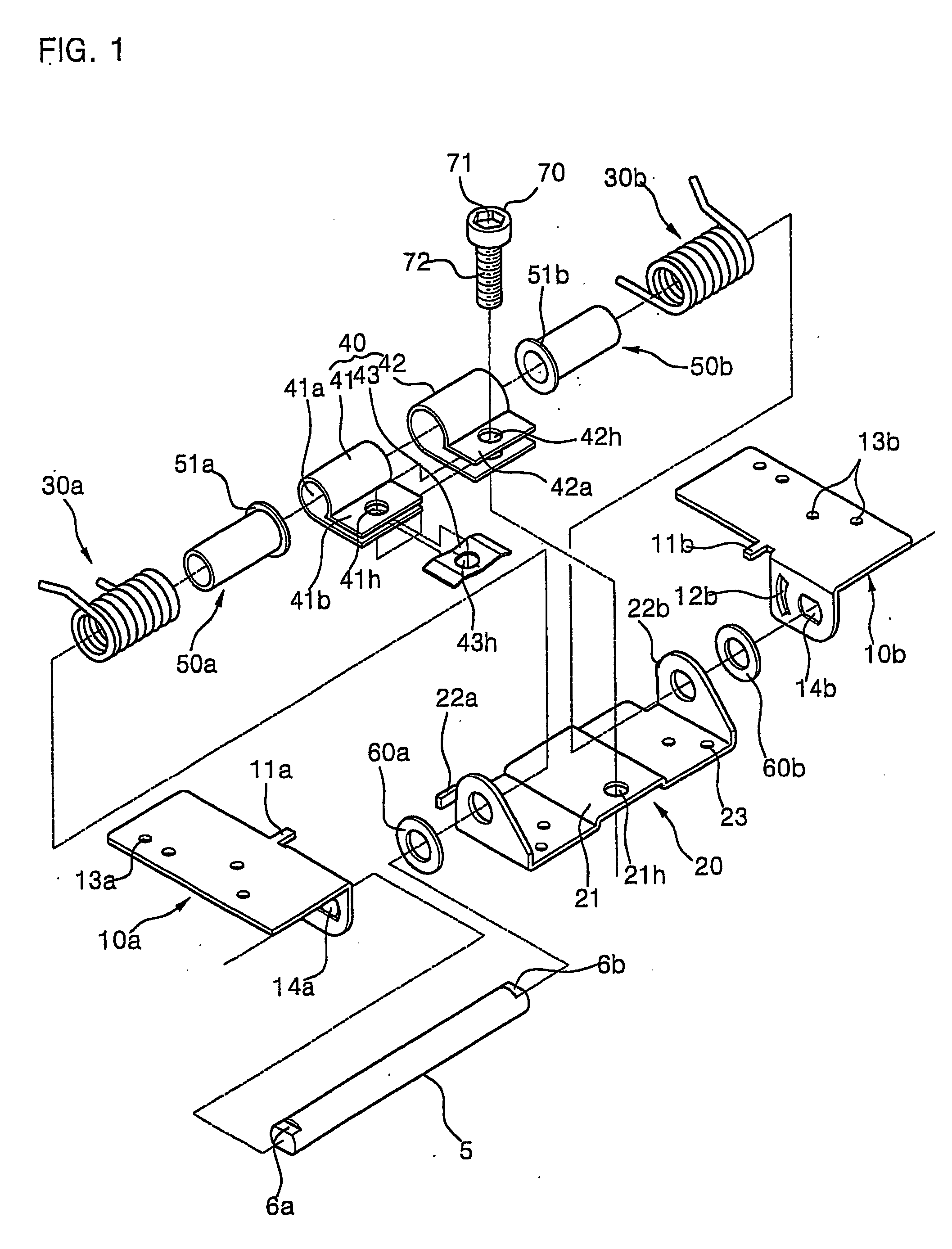
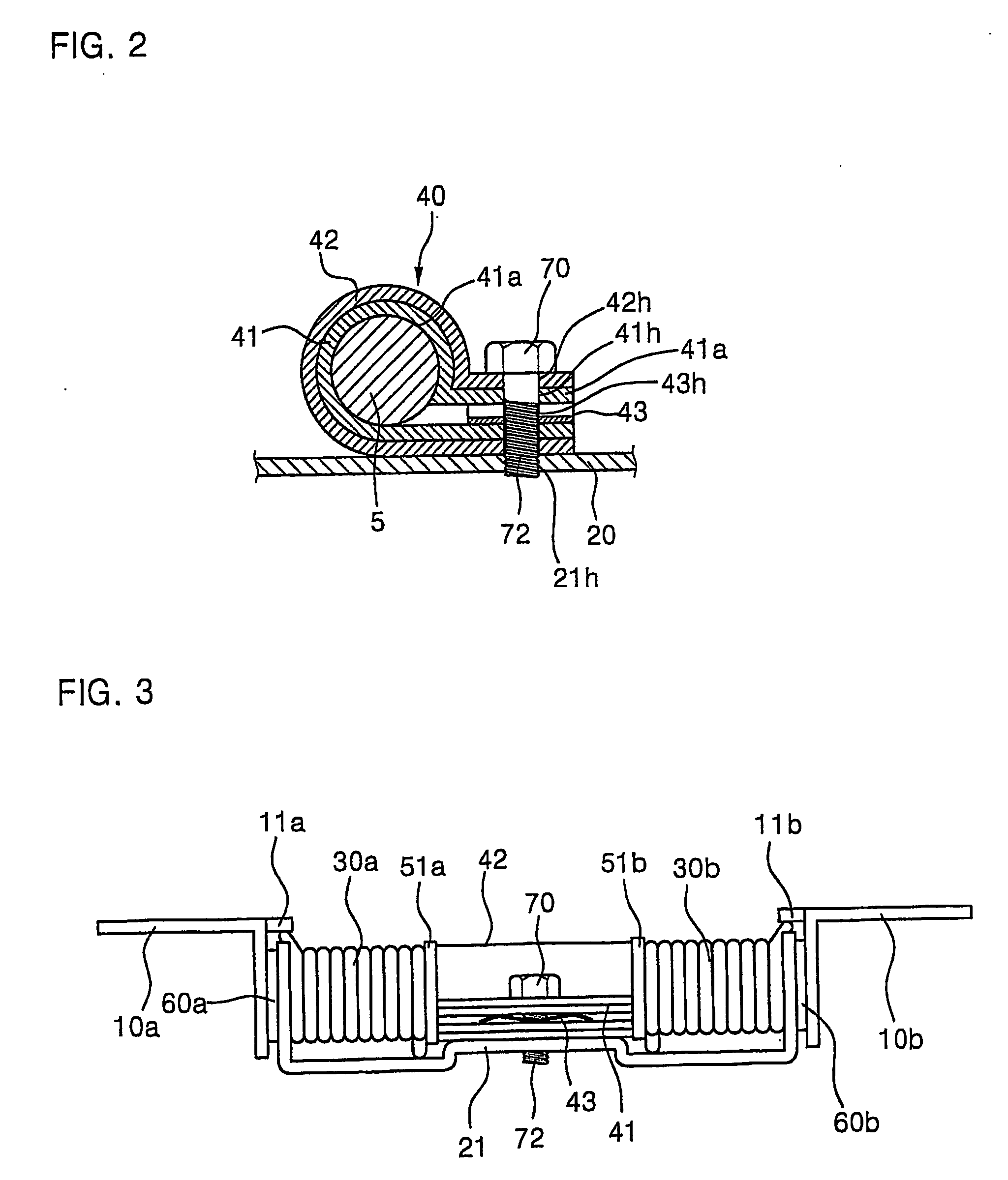
[0021] A preferred embodiment of a hinge structure for a flat visual display device according to the present invention will now be described with reference to the accompanying drawings. In the following description, same drawing reference numerals are used for the same elements even in different drawings. The matters defined in the description such as a detailed construction and elements of a hinge structure are nothing but the ones provided to assist in a comprehensive understanding of the invention. Thus, it is apparent that the present invention can be carried out, not limited to those defined matters. Also, well-known functions or constructions are not described in detail since they would obscure the invention in unnecessary detail.

[0022]FIG. 1 is an exploded perspective view of a hinge structure for a flat visual display device according to the present invention. Referring to FIG. 1, a hinge structure according to the present invention can be explained in the following: in whi...


PUM


Abstract

A hinge structure for a flat visual display device comprising: a pivotal plate connected to the flat visual display device; a fixing plate connected to a supporting portion for supporting the flat visual display device; a rotational shaft inserted to vertical planes of the pivotal plate and the fixing plate, for rotation of the flat visual display device in one degree of freedom; a frictional member which is formed on an outer periphery of the rotational shaft for enclosing the rotational shaft, and whose both ends have a frictional member tightening plane of a planar shape on which a second inserting hole is formed; and a tightening member inserted to the second inserting hole, for tightening the frictional member tightening plane, thereby tightening the rotational shaft by means of the frictional member, and generating strong breaking force accordingly.

Description

TECHNICAL FIELD [0001] The present invention relates to a hinge structure, and more particularly, to a hinge structure for a flat visual display device, wherein the hinge is used as a fabrication between two members on which the hinge is applied, whereby the two members operate smoothly and braking force due to proper frictional force is provided. BACKGROUND ART [0002] Common household articles have adopted lots of conventional hinge structures where in order for their movement of one degree of freedom to up and down or right and left, rotational member and fixing member are connected on the same shaft, so that relative rotational motion is generated between the fixing member and the rotational member. [0003] More detailed explanation can be made with following examples for product operation on which such hinge structure is applied, which includes predetermined operation such as open or shut of product cap, open or shut of upper side in notebook computer, up and down adjustment of a...

Claims


Application Information

Patent Timeline
Patent Type & Authority Applications(United States)
IPC IPC(8): G06F1/16
CPCG06F1/1601Y10T16/5403Y10T16/54038Y10T16/5385G06F1/16
Inventor LEE, GANG-HOONKIM, HONG KI
Owner LG ELECTRONICS INC
Learn More