

Oil circulation observer for HVAC systems
a technology of hvac systems and oil circulation observer, which is applied in the direction of refrigeration machines, lighting and heating apparatus, and refrigeration safety arrangements, etc. it can solve the problems of high oil viscosity, insufficient oil in the compressor, and insufficient lubrication of the compressor
Inactive Publication Date: 2005-05-19
MASSACHUSETTS INST OF TECH
View PDF6 Cites 19 Cited by
- Summary
- Abstract
- Description
- Claims
- Application Information
AI Technical Summary
Benefits of technology
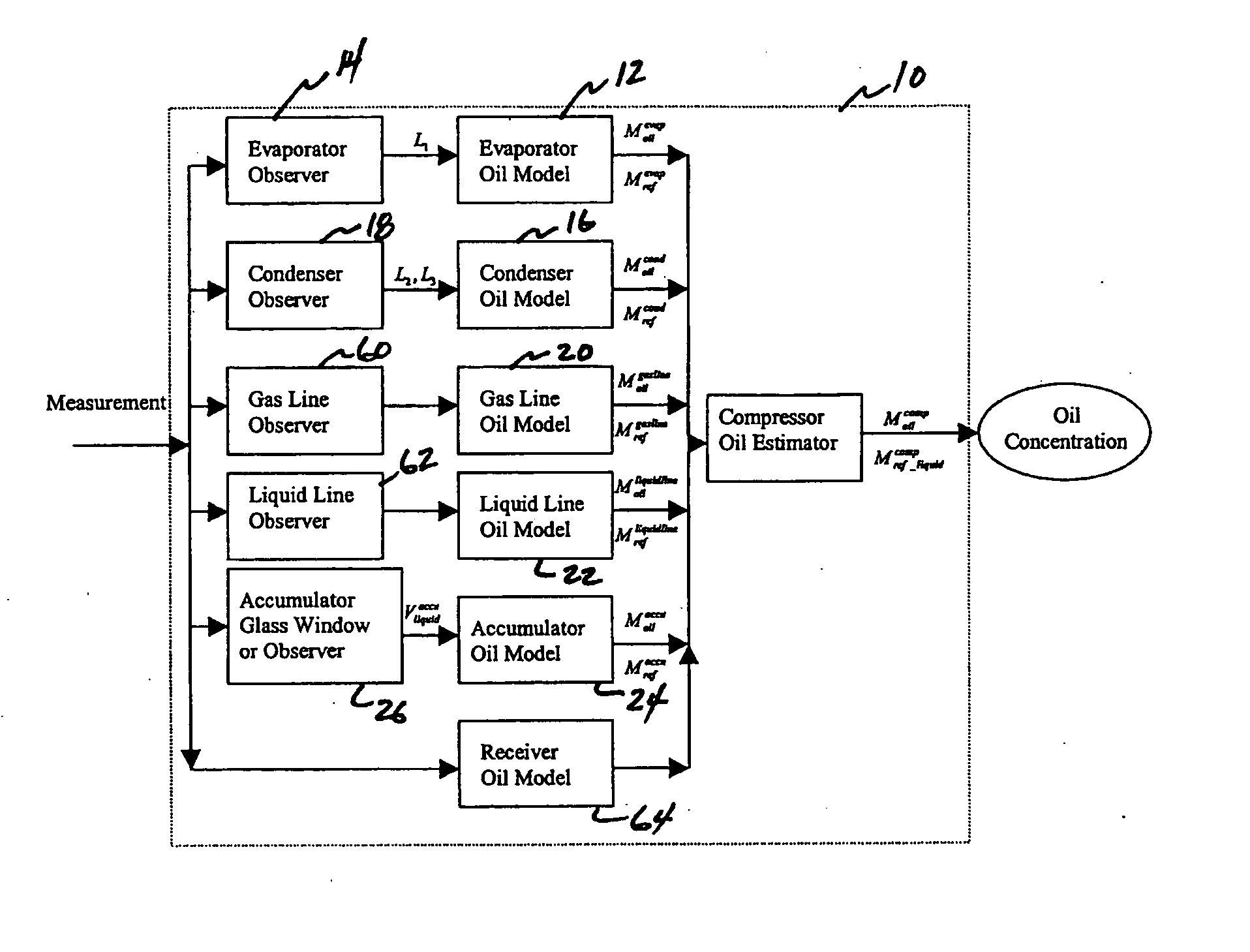
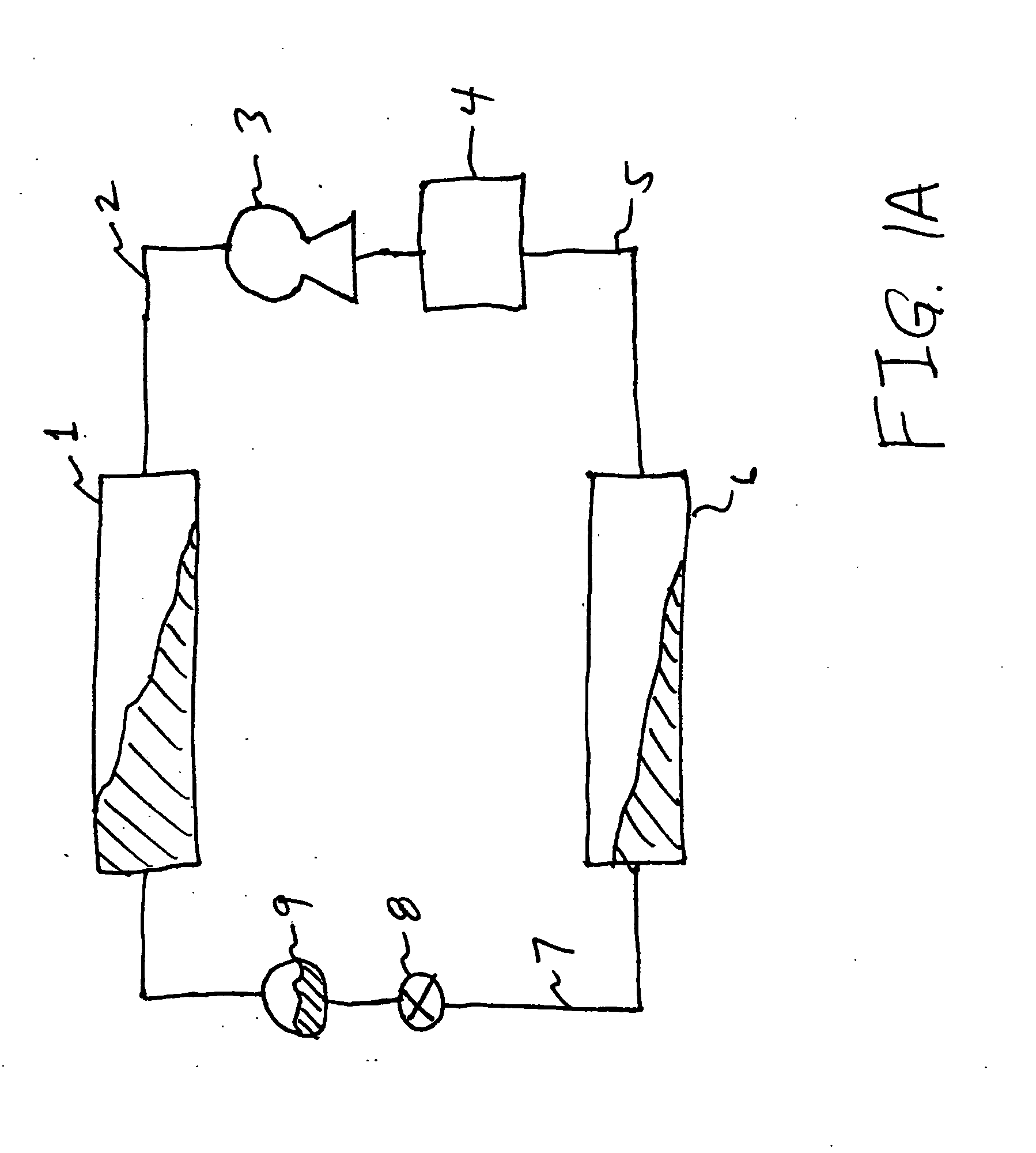
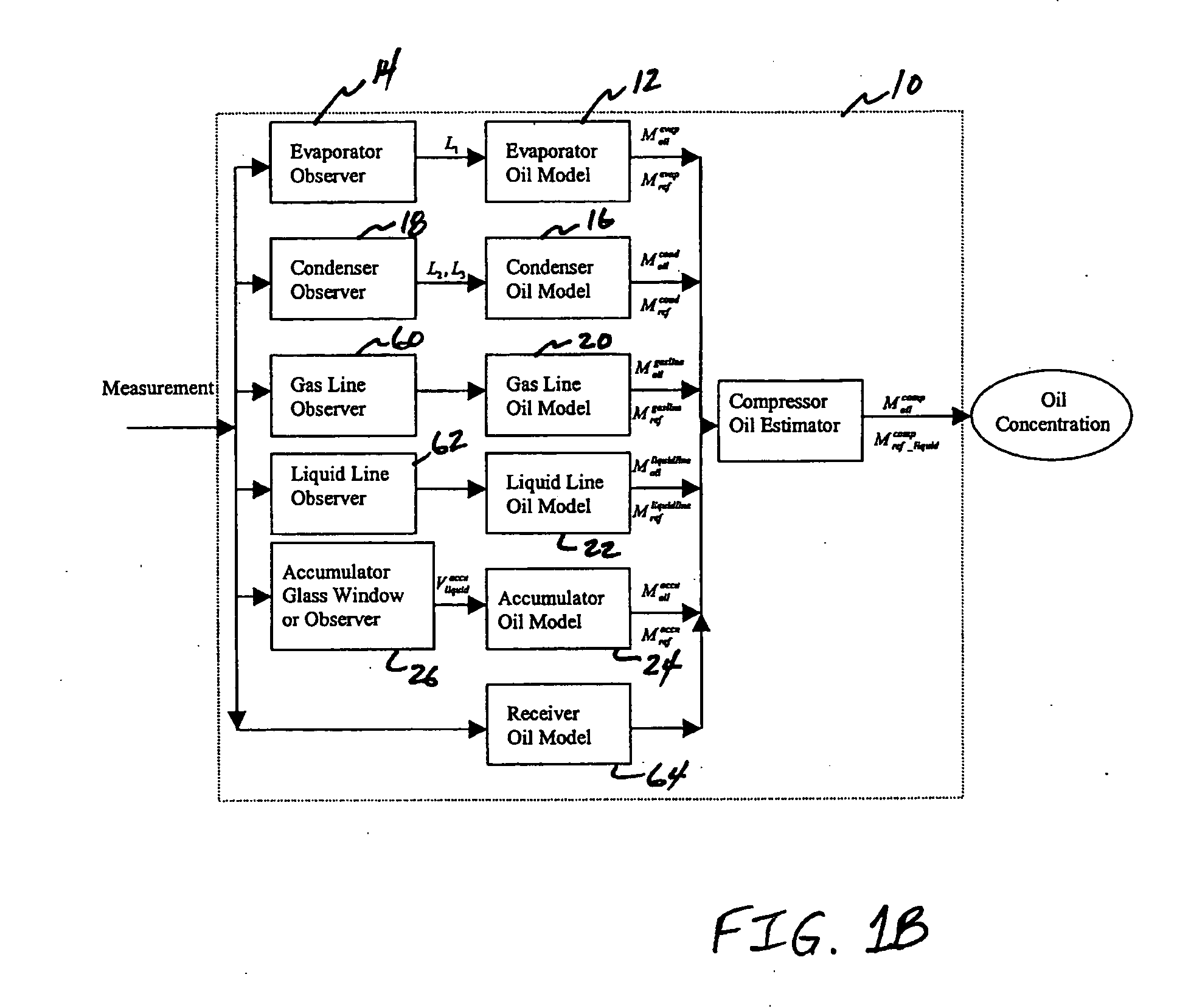
[0009] In one embodiment, the first component of the vapor compression cycle system is a compressor. The plurality of other components of the vapor compression cycle system can comprise at least one of an evaporator, an accumulator, a suction gas line, a discharge gas line, a
Problems solved by technology
For example, this may happen when the defrost operation is turned on during the heating season, since under such conditions, the indoor fan is typically shut down, and liquid in the evaporator may not be evaporated.
As a result, large amounts of liquid refrigerant may enter the compressor chamber and mix with the lubricating oil.
However, in an evaporator, when superheat is large and evaporating temperature is low, oil viscosity may become high because liquid refrigerant becomes vapor in the superheat range.
If vapor velocity is not sufficient to transport the oil, some oil may remain in the evaporator.
Similarly, in suction lines, oil retention may be
Method used
View moreImage
Smart ImageViewing Examples

Examples
 PUM
 Abstract
An innovative oil observer for estimating oil concentration and oil amount in a refrigerant compressor in a vapor compression cycle is described. The invention ensures the safe operation of the compressor by ensuring that adequate lubricant is present in the compressor. This oil observer is based on oil models for components of air conditioning and refrigeration systems. Oil models for HVAC components estimate oil mass and refrigerant mass in each component. With all component oil models and heat exchanger observers which provide the estimation of inner geometric lengths of two-phase flow heat exchangers, a system-level oil observer is established by integrating all component models. Experimental testing has been conducted to verify the performance of this oil observer for steady state operation and dynamic processes. The invention has direct applications in residential and commercial air conditioning and refrigeration systems.
Description
RELATED APPLICATION [0001] This application is based on U.S. Provisional Application Ser. No. 60 / 523,447, filed on Nov. 19, 2003, the contents of which are incorporated herein in their entirety by reference.BACKGROUND OF THE INVENTION [0002] Lubricating oil in the compressor of a heating, ventilation and air conditioning (HVAC) system provides lubrication for moving parts in the compressor. Good lubrication ensures the safe operation of the compressor. For a refrigerant compressor, the oil lubricating capability decreases when the oil is mixed with liquid refrigerant. For example, this may happen when the defrost operation is turned on during the heating season, since under such conditions, the indoor fan is typically shut down, and liquid in the evaporator may not be evaporated. As a result, large amounts of liquid refrigerant may enter the compressor chamber and mix with the lubricating oil. [0003] To quantify how much liquid refrigerant is mixed with oil in the compressor, an imp...
Claims
Login to View More Application Information
Patent Timeline
 IPC IPC(8): F25B49/02F25B31/00
CPCF25B31/002F25B2700/03F25B2500/16
InventorHE, XIANG-DONGASADA, H. HARRYCHENG, TAO
OwnerMASSACHUSETTS INST OF TECH