Unbonded system for strength testing of concrete cylinders

a technology of unbonded system and concrete, which is applied in the direction of measuring device, fluid pressure measurement using elastically deformable gauges, instruments, etc., can solve the problems of compression pads that fall out of the retaining cups frequently, and the procedure requires considerable preparation tim

a technology of unbonded system and concrete, which is applied in the direction of measuring device, fluid pressure measurement using elastically deformable gauges, instruments, etc., can solve the problems of compression pads that fall out of the retaining cups frequently, and the procedure requires considerable preparation tim

US20050103118A1Inactive Publication Date: 2005-05-19DESLAURIERS

Image

  • Unbonded system for strength testing of concrete cylinders
  • Unbonded system for strength testing of concrete cylinders
  • Unbonded system for strength testing of concrete cylinders

Examples


Embodiment Construction

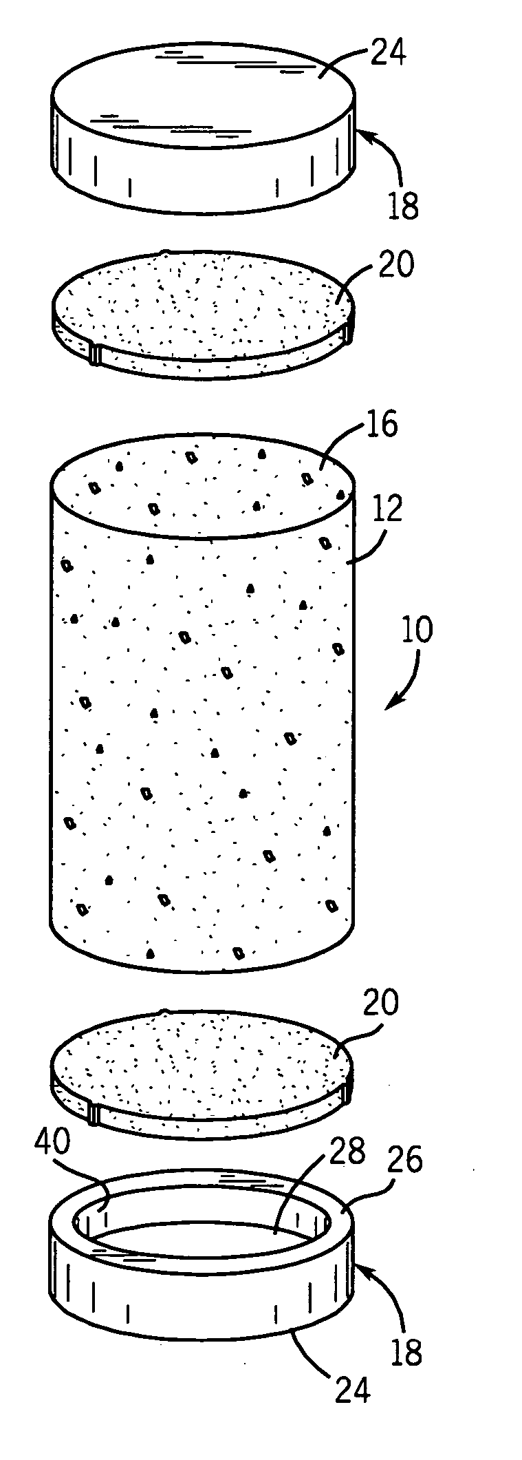
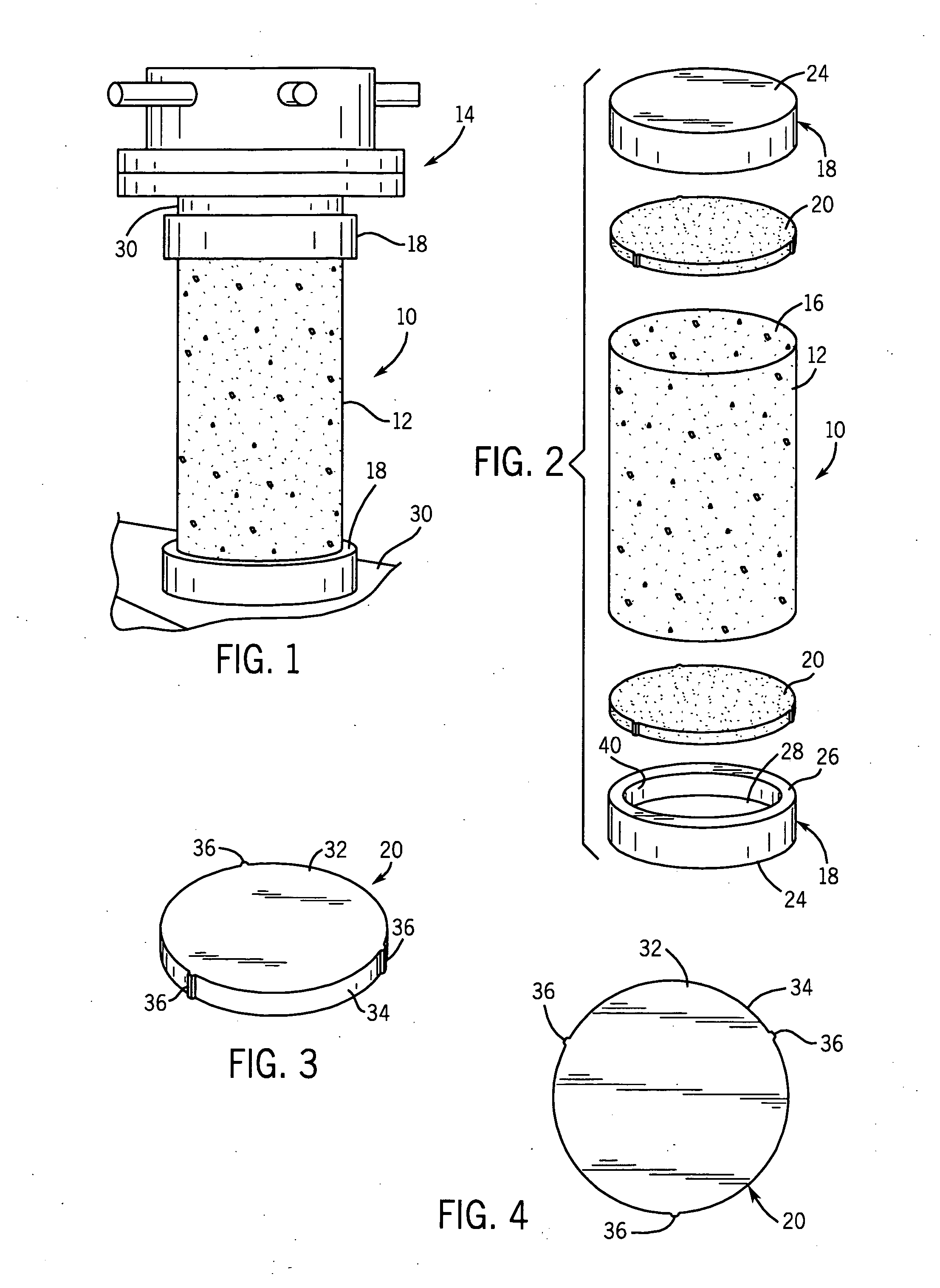
[0017] In accordance with the invention, there is provided an unbonded capping system 10, see FIGS. 1 and 2, for compression testing of a concrete cylinder 12. The unbonded capping system 10 is adapted to be used with a compression testing apparatus or fixture 14, see FIG. 1.

[0018] The concrete cylinder 12 can be formed using any known technique. Conventionally, an end wall 16 of the concrete cylinder 12 is approximately six inches in diameter. The height of the concrete cylinder 12 is approximately twelve inches. Alternatively, the concrete cylinder 12 may be four inches in diameter and eight inches long. As is apparent, depending on the procedure used for forming the concrete cylinder 12, the exact dimensions may vary.

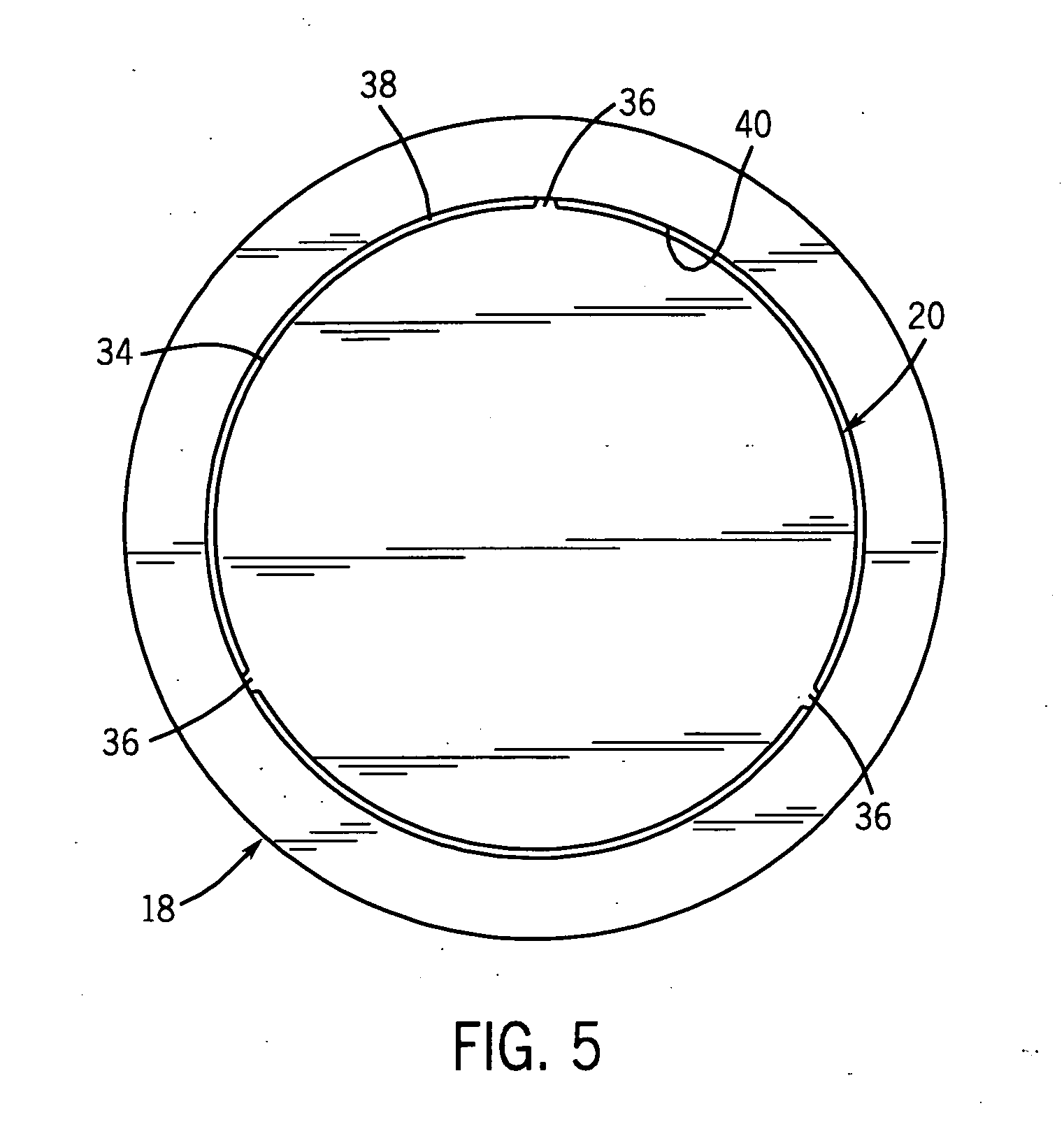
[0019] The unbonded capping system 10 comprises first and second retaining cups 18 and first and second compression pads 20. Each of the retaining cups 18 is identical in construction. Similarly, each compression paid 20 is identical in construction.

[0020] Each re...


PUM

PropertyMeasurementUnit
heightaaaaaaaaaa
heightaaaaaaaaaa
diameteraaaaaaaaaa

Abstract

An unbonded capping system for compression testing of concrete cylinders comprises first and second retaining cups comprising metal blocks each having opposite parallel planar surfaces. A first of the planar surfaces is engageable by a test apparatus, in use. A second of the planar surfaces has a cylindrical cavity of a first select diameter for receiving one end of the concrete cylinder. First and second cylindrical compression pads are each to be received in one of the retaining cup cavities to abut an end of the concrete cylinder, in use. The compression pads are of a second select diameter smaller than the first select diameter of the cavity to define a circumferential space therebetween. Nubs are provided for gripping the cavity to prevent the compression pads from falling out of the cavities.

Description

FILED OF THE INVENTION [0001] This invention relates to compression testing of concrete samples and, more particularly, to an unbonded capping system. BACKGROUND OF THE INVENTION [0002] Various tests have been developed to ensure that concrete used in particular applications satisfies specifications. One of these is a compression test for testing concrete cylinders. Initially, the tests were performed by capping freshly molding concrete cylinders with materials such as sulfur mortar. This provides a smooth, hard surface which fills any imperfections which normally occur when making the concrete cylinder. These procedures require considerable preparation time. [0003] More recently, unbonded capping systems have been developed. A typical unbonded capping system comprises a pair of retaining cups and a pair of compression pads. Each retaining cup retains one of the compression pads and fits over one end of the concrete cylinder. This assembly is then placed between the platens of a com...

Claims


Application Information

Patent Timeline
19 May 2005
Publication
US20050103118A1
IPC
G01N3/02; G01N3/04; G01N3/08; G01N33/38
CPC
G01N3/08; G01N33/383; G01N2203/0441; G01N2203/0298; G01N2203/0266
Inventors
WORKMAN, GARY