Lockout mechanism for a suspension system

a technology of suspension system and lockout mechanism, which is applied in the direction of shock absorbers, steering devices, cycle equipment, etc., can solve the problems of dissipating the energy of the rider, damage to the system, and the up and down bobbing motion of the bicycl

Active Publication Date: 2005-05-19
SRAM CORPORATION
View PDF19 Cites 91 Cited by
  • Summary
  • Abstract
  • Description
  • Claims
  • Application Information

AI Technical Summary

Benefits of technology

[0011] The blow-off pressure at which the valve mechanism opens may be adjusted by the rider. The stiffness of the resilient member, as it is compressed to close the gap between the valve mechanism and the driver, determines the pressure at which the valve mechanism will blow-off. The dis

Problems solved by technology

The pedaling action of the rider loads the suspension, resulting in up and down bobbing motion of the bicycle.
Generally however, on smooth terrain, this motion dissipates the rider's energy, energy that could be used to propel the bicycle forward.
One problem associated with prior art lockout mechanisms is that damage may occur to the system while in the lockout mode under a large jarring compression load.
There are several problems with this configuration including the comple

Method used


Image

  • Lockout mechanism for a suspension system
  • Lockout mechanism for a suspension system
  • Lockout mechanism for a suspension system

Examples


Embodiment Construction

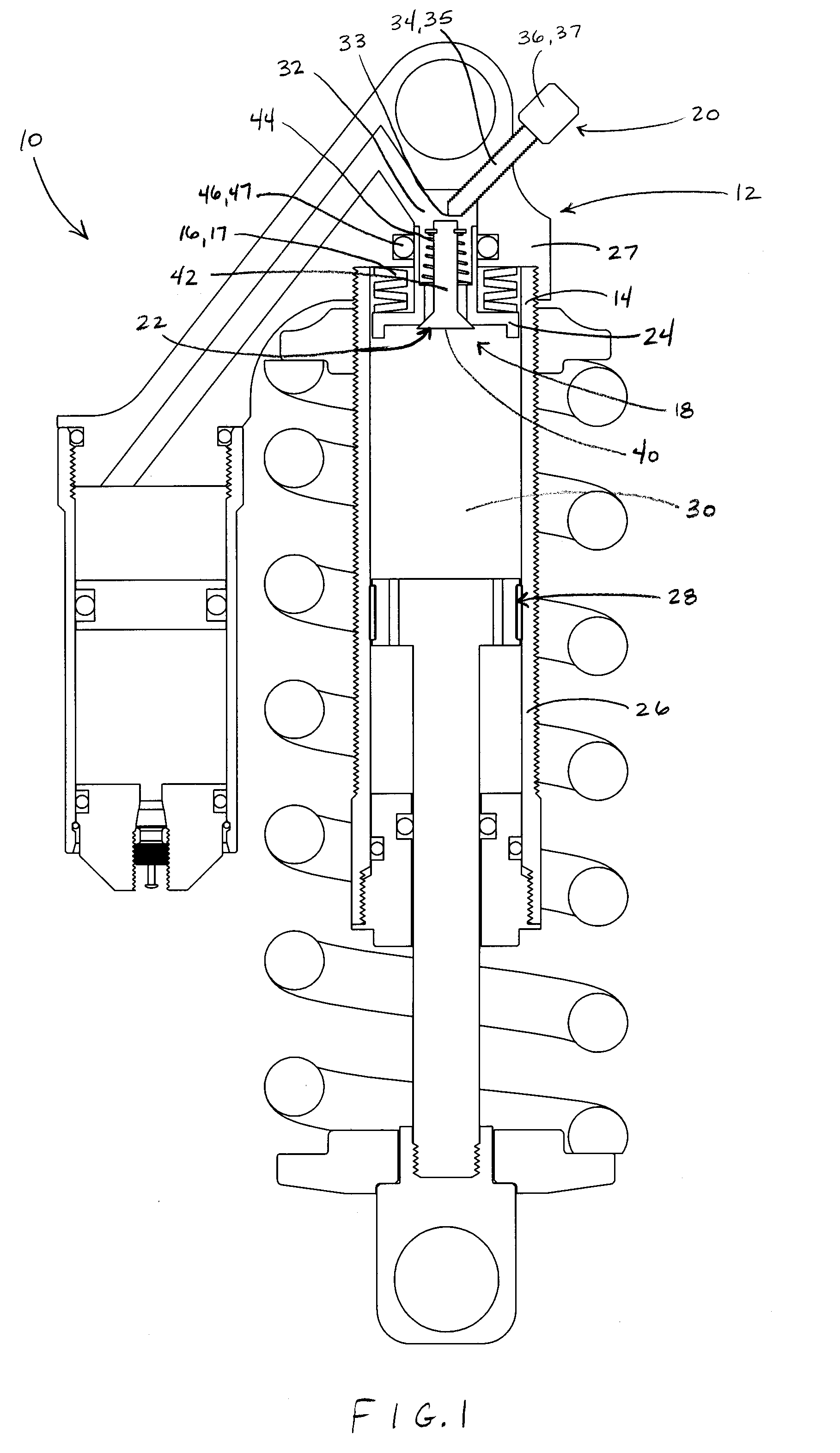
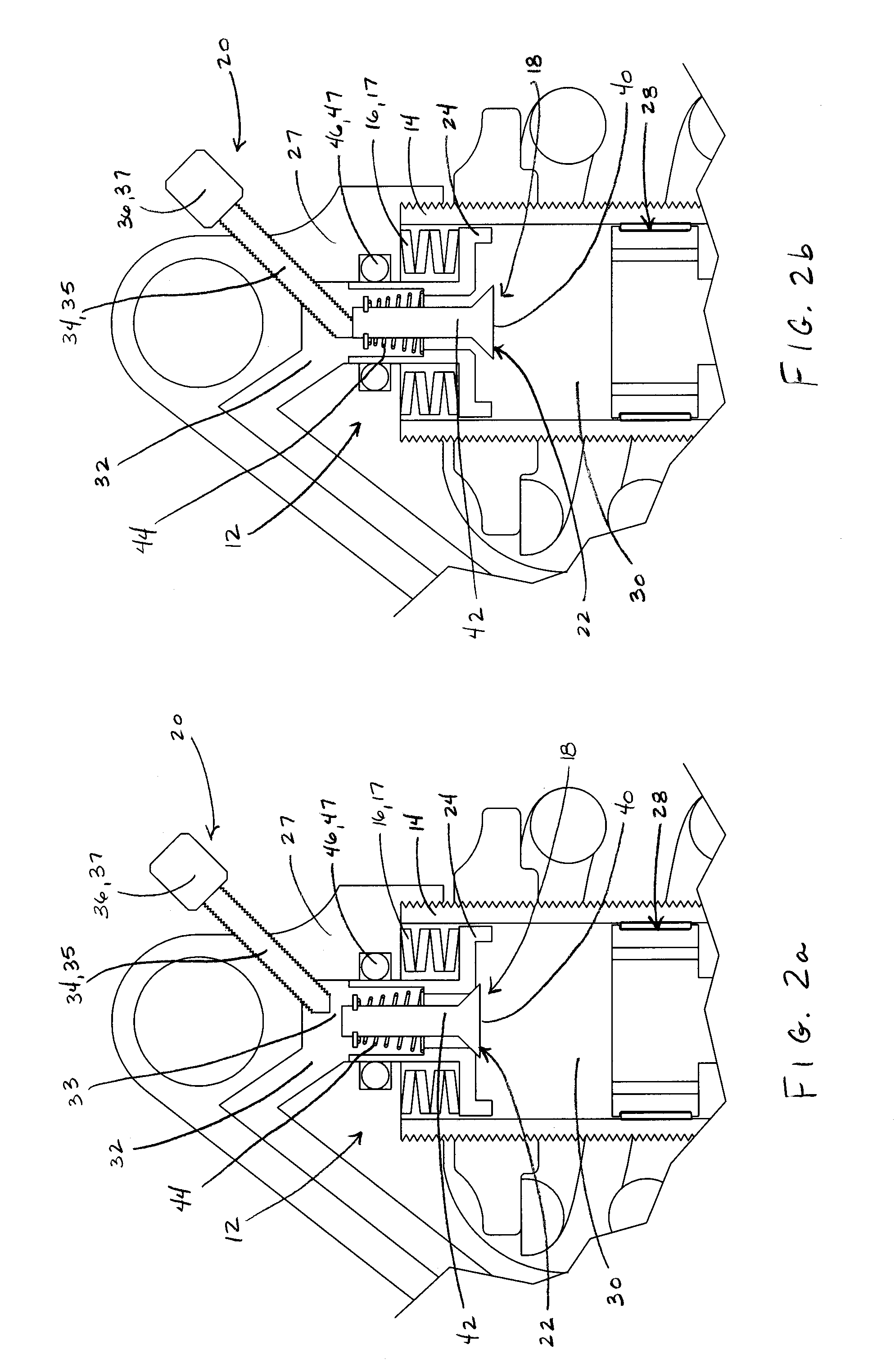
[0040] A suspension system 10 is shown in FIGS. 1-3 comprising a lockout mechanism 12, a valve mechanism housing 14, and a resilient member 16. The lockout mechanism includes a valve mechanism 18 and a valve actuating assembly 20. The valve mechanism 18 includes a valve 22 and a valve seat 24, the valve 22 displaceable relative to the valve seat 24, and in turn, the valve seat 24 and the valve mechanism 18 slidably mounted along the valve mechanism housing 14. In the embodiment of FIGS. 1-3, the valve mechanism housing 14 forms a portion of a piston tube 26 within which a compression piston assembly 28 is slidably mounted. The valve mechanism 18 separates a first fluid chamber 30 from a second fluid chamber 32 and controls fluid flow therebetween. The piston assembly 28 is displaceable toward the valve mechanism 18 to increase the fluid pressure in the first chamber 30.

[0041] The valve actuating assembly 20 further includes a driver 34 that is displaceable relative to the valve mec...


PUM


Abstract

A suspension system that includes a simplified lockout mechanism and an adjustable blow-off mechanism. The system includes a valve mechanism and a valve actuating assembly, a valve mechanism housing and a resilient member disposed between the valve mechanism and the valve mechanism housing. The valve mechanism is slidably mounted along the valve mechanism housing and it separates a first chamber from a second chamber. The valve actuating assembly operates the valve mechanism between open and closed positions. The resilient member is configured to be deformable by the valve mechanism as the valve mechanism is slidably displaced by an increasing pressure in the first fluid chamber. The sliding valve mechanism is configured to collide against the valve actuating assembly when a blow-off pressure is reached in the first fluid chamber switching the valve mechanism from the closed position to the open position.

Description

BACKGROUND OF INVENTION [0001] The present invention relates to suspension systems and more particularly to a simplified lockout device for a suspension system that includes an adjustable “blow-off” mechanism. The present invention also relates to a simplified flow restrictive device for a suspension system that includes an adjustable pressure relief mechanism. [0002] Suspension systems, typically used on handlebar-steered vehicles such as bicycles and motorcycles, are designed to absorb the impacts and vibrations typically experienced by riders when the bicycle traverses irregularities on the riding surface. Suspension systems may be positioned in or proximate to the front and rear forks, seat tube, head tube, and other bicycle frame locations to insulate the rider from vibrations and impacts. Suspension performance may be affected by various factors such as rider weight, rider skill and terrain conditions. One particular factor that may affect suspension performance is rider induc...

Claims


Application Information

Patent Timeline
IPC IPC(8): B62K25/04B62K25/08F16F9/00F16F9/44F16F9/516F16F9/56
CPCB62K25/08F16F9/003F16F9/56F16F9/516F16F9/446Y10T137/7775
Inventor WESLING, KEVIN F.JORDAN, BRIAN T.SHIPMAN, CHRISTOPHER A.CHEEVER, JOHN D.HERRINGTON, EDWARDOSBORNE, JAMES
Owner SRAM CORPORATION
Why Eureka
Try Eureka