Portable electronic apparatus

a technology of electronic equipment and portability, applied in the direction of cathode-ray tube indicators, instruments, etc., can solve the problems of low battery capacity, difficult operation with constant power on from the viewpoint of commercial value, and relatively high power consumption, and achieve the effect of reducing the lit time ratio

Inactive Publication Date: 2005-05-19
MASAKI HIROYUKI
View PDF11 Cites 15 Cited by
  • Summary
  • Abstract
  • Description
  • Claims
  • Application Information

AI Technical Summary

Benefits of technology

[0026] Further, the apparatus may be configured such that the display brightness control means: controls the display means to cause the segment selected by the manipulati

Problems solved by technology

On the other hand, in the case of using a self-luminous element such as an EL, an organic EL, or an LED for a display device, the power consumption is relatively high, so that the operation with the power turned on constantly is difficult from the viewpoint of a commercial value.
For example, if the device is operated with the power turned on constantly using a battery installed in a compact portable apparatus such as a watch, the battery capacity becomes too low in a few hours or in a few days, rendering the device practically unusable.
However, in the case of structuring an electronic watch by using the inventions disclosed in Patent Documents 1 to 5, the display is continuously turned on in such a state as to allow a watch function that requires constant power supply and otherwise would be useless, for example, a chr

Method used


Image

  • Portable electronic apparatus
  • Portable electronic apparatus
  • Portable electronic apparatus

Examples


first embodiment

[0053] Hereinafter, description will be made of the first embodiment referring to FIGS. 1 to 4.

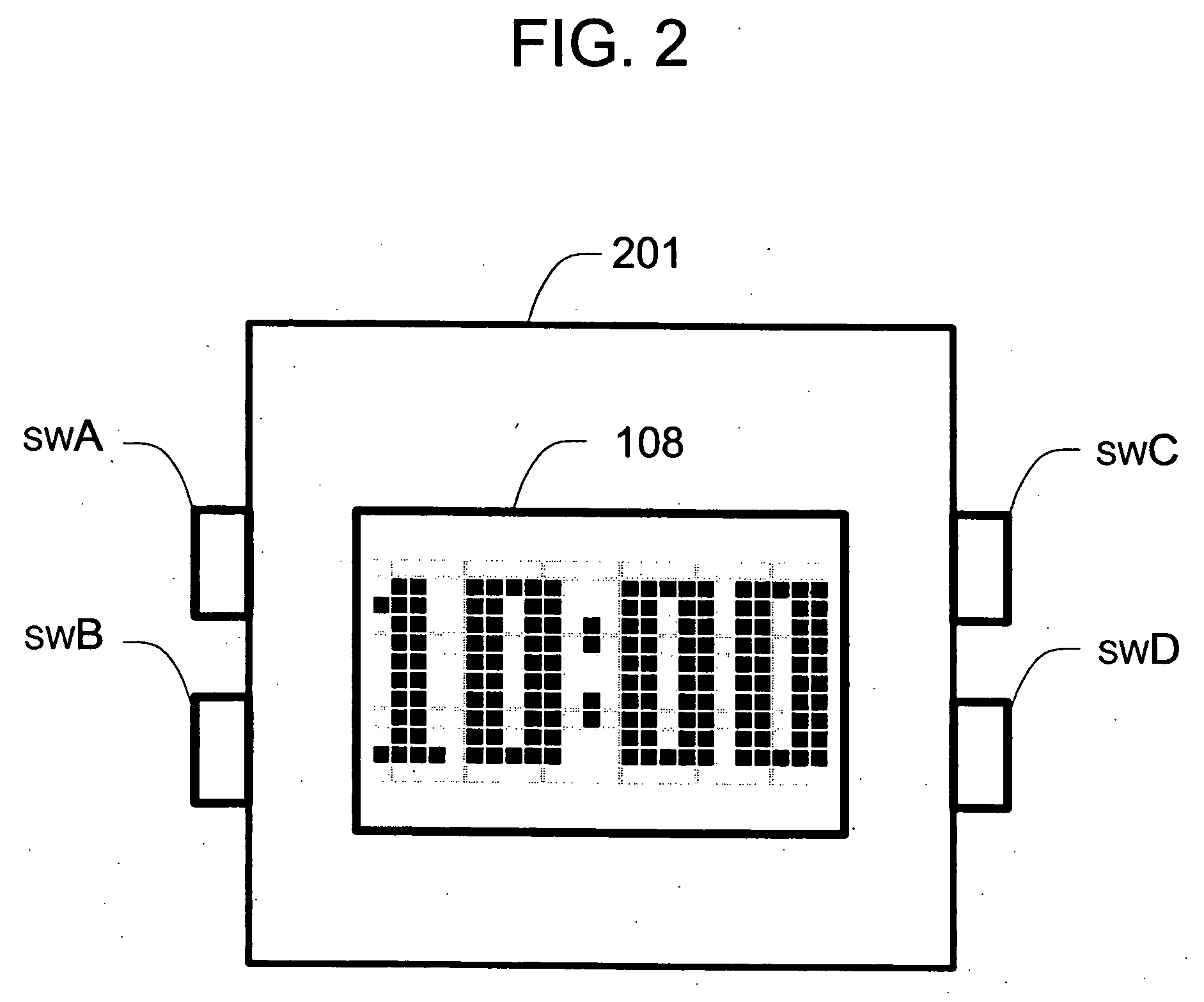
[0054] In order to enter a time modification mode that is a kind of data setting mode, the manipulation switch swB is subjected to predetermined manipulation (step S401 of FIG. 4) in a normal time display mode (see 2-A of FIG. 3). The state detecting means 109 then notifies the display control means 106 of the predetermined manipulation of the manipulation switch swB. Based on the notification, the display control means 106 judges whether or not the manipulation switch swB has been subjected to the predetermined manipulation (step S402).

[0055] Upon the judgment that the manipulation switch swB has been subjected to predetermined manipulation in the normal time display mode, the display control means 106 controls the display means 108 to change the brightness and the font size between the necessary segment for time modification and the other segments.

[0056] More specifically, the display ...

second embodiment

[0068] Hereinafter, description will be made of the second embodiment referring to FIGS. 1, 2, 5, and 6.

[0069] In order to enter the data setting mode for time modification, data rewriting, or the like, the manipulation switch swB is subjected to predetermined manipulation (step S601 of FIG. 6) in a time display mode (see 3-A of FIG. 5). The timer means 105 then starts time counting operation (step S602), and the state detecting means 109 notifies the display control means 106 of the predetermined manipulation of the manipulation switch swB.

[0070] The display control means 106 causes a segment for data setting to blink at a predetermined cycle (0.5-second cycle in the second embodiment) in response to the predetermined manipulation of the manipulation switch swB (see 3-B and 3-C of FIG. 5). Note that the sequence of segments for data setting is previously set in storage means of the display control means 106. In the case of performing data setting on a plurality of segments, in res...

third embodiment

[0082] Hereinafter, description will be made of the third embodiment referring to FIGS. 1, 2, 7, and 8.

[0083] In order to start the time counting operation, the manipulation switch swC is subjected to predetermined manipulation (step S801 of FIG. 8) in a state where the chronograph mode is entered (see 4-A of FIG. 7). The state detecting means 109 then notifies the display control means 106 of the predetermined manipulation of the manipulation switch swC. Based on the notification, the display control means 106 judges whether or not the manipulation has been performed for starting or stopping the chronograph function (step S802).

[0084] Upon the judgment that the manipulation has been performed for starting the chronograph function in step S802, the display control means 106 controls the display means 108 such that all the segments for displaying an elapsing time are displayed at the first brightness level being high (a brightness level of 10 in the third embodiment) (see 4-B of FIG...


PUM


Abstract

A portable electronic apparatus has a display for displaying display segments. A selecting circuit selects one of the display segments displayed by the display. A display brightness controller controls the display so that the display segment selected by the selecting circuit has a display brightness higher than that of the other display segments displayed by the display.

Description

BACKGROUND OF THE INVENTION [0001] 1. Field of the Invention [0002] The present invention relates to a portable electronic apparatus such as an electronic watch that displays time and the like, and particularly to a portable electronic apparatus preferred when equipped with a digital display device of a self-luminous type. [0003] 2. Description of the Prior Art [0004] Conventionally, when time data or other such data is displayed in a portable apparatus equipped with a display device such as a liquid crystal panel, the power consumed by the panel itself is extremely low, so that the display is usually performed with the power turned on constantly. However, according to the invention as disclosed in Patent Document 1, there is a rechargeable electronic watch in which a display device is driven in one optimum mode selected from a plurality of clock operation modes different in power consumption according to power generation volume. [0005] In order to render the display visible under a...

Claims


Application Information

Patent Timeline
IPC IPC(8): G04G9/00G04G5/04G04G9/08G06F3/048G06F3/0484G09G3/20G09G3/30G09G3/32G09G5/24
CPCG09G5/24G04G5/04
Inventor MASAKI, HIROYUKI
Owner MASAKI HIROYUKI
Why Eureka
Try Eureka