
Internal lift for light duty motor vehicle

a technology for motor vehicles and lifts, applied in the direction of loading/unloading vehicles, transportation items, refuse collection, etc., can solve the problems of increasing vehicle length, heavy weight, and inconvenient terminology

Inactive Publication Date: 2005-05-19
VANTAGE MOBILITY INT
View PDF17 Cites 23 Cited by
  • Summary
  • Abstract
  • Description
  • Claims
  • Application Information

AI Technical Summary

Benefits of technology

[0010] Another object of the invention is to provides adequate location for the goods, i.e

Problems solved by technology

These scooters are battery powered, ride on either three or four small wheels, and are relatively compact but can be rather heavy because of the battery and electric motor.
Powered wheelchairs and scooters are evolving toward each other, making terminology imprecise.
Further, such a lift increases vehicle length and substantially changes the driving characteristics of the vehicle when carrying a scooter.
An interior lift typically hooks onto a scooter in two or more places but does not prevent the scooter from turning, which can make it difficult to load the scooter.
Such lifts are quite expensive, often too expensive for those who need the lift.
Enclosed platforms often take up a substantial amount of interior space, which can be a problem is smaller vehicles such as a minivan.
Station wagons, utility vehicles, pick-up trucks, and other light duty motor vehicles are unlikely candidates for such lifts because of lack of space or lack of weather protection.
This is needlessly inconvenient and potentially dangerous because the entrance to the platform is often on the driver's side or traffic side of the vehicle; e.g. see the Peterson patent.
Another inconvenience in lifts of the prior art having more than one powered axis of movement is a control system that has a separate button for each axis.

Method used


Image

  • Internal lift for light duty motor vehicle
  • Internal lift for light duty motor vehicle
  • Internal lift for light duty motor vehicle

Examples


Embodiment Construction

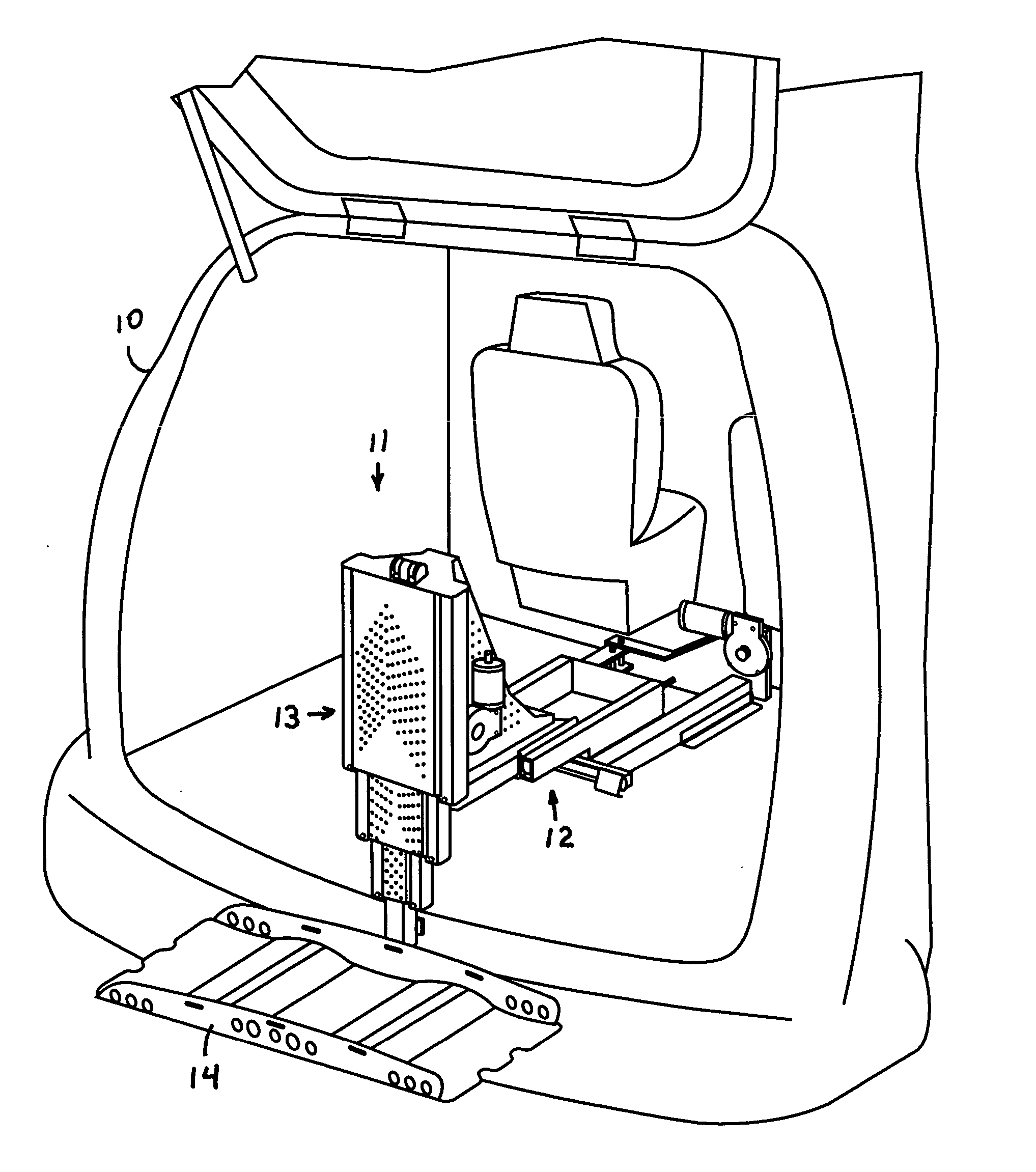
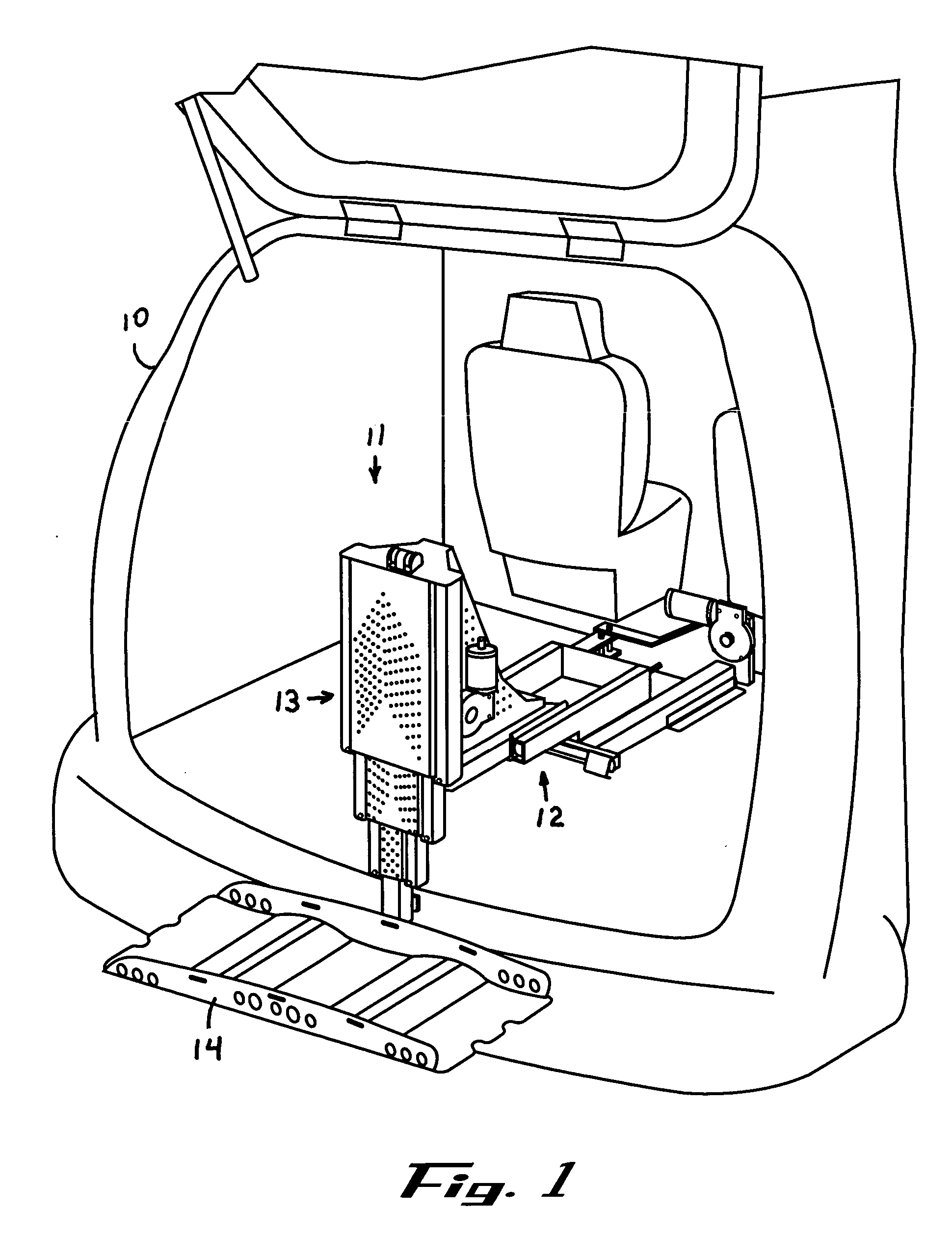
[0036]FIG. 1 is a perspective view of a lift constructed in accordance with the invention and mounted in a light duty motor vehicle, represented by minivan 10. Lift 11 includes two telescoping members, horizontally telescoping member 12 and vertically telescoping mast 13. The lower portion of vertically telescoping mast 13 is attached to platform 14. As illustrated in FIG. 1, platform 14 is adapted to receive a motorized scooter. As further described below, a variety of tools can be attached to the moving end of vertically telescoping mast 13 to adapt the lift to a wide variety of tasks.

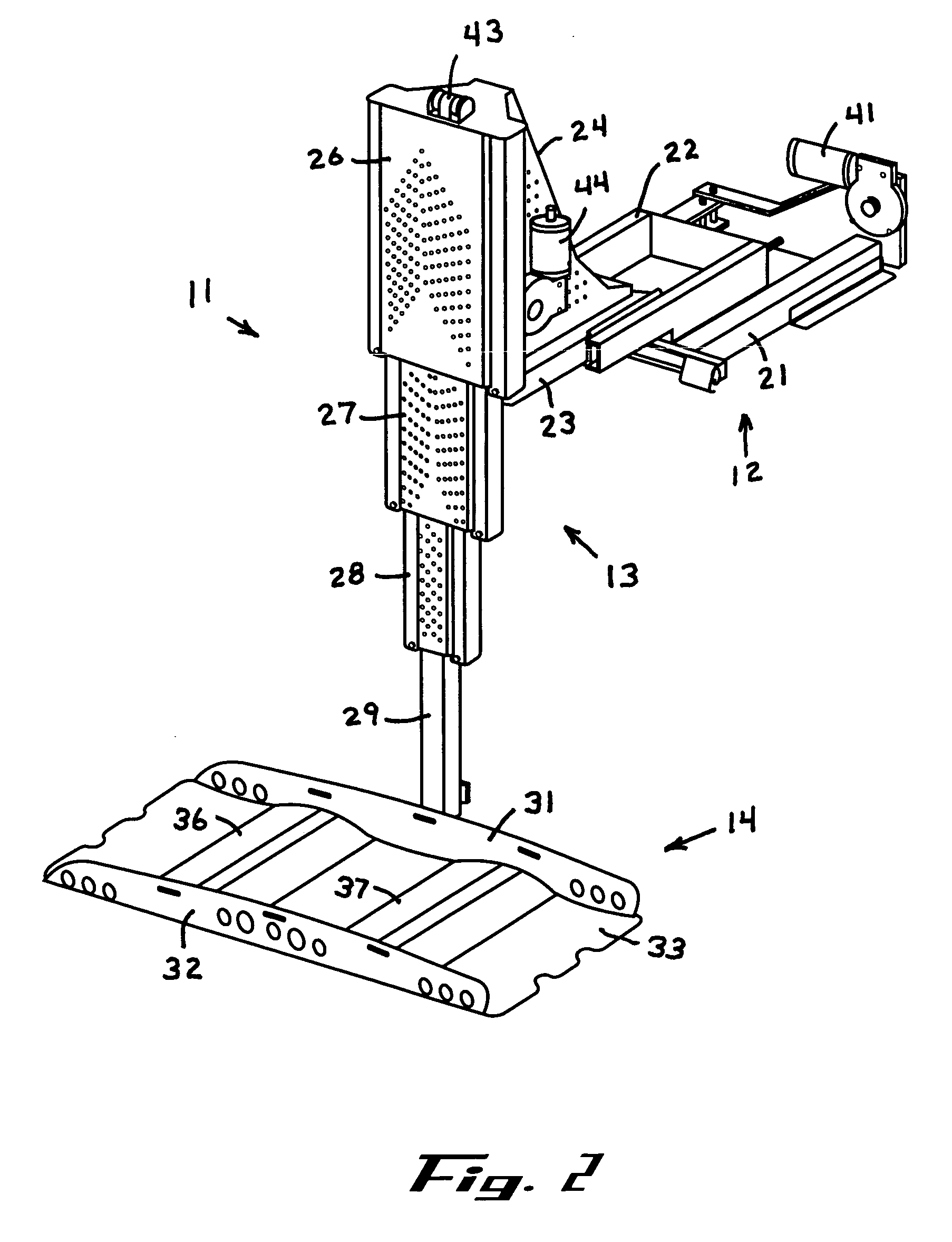
[0037]FIG. 2 illustrates lift 11 fully extended horizontally and vertically. Horizontally telescoping member 12 includes base 21, middle slide 22, and inner slide 23 including head 24 to which vertically telescoping mast 13 is attached, preferably by welding. Vertically telescoping mast 13 includes base unit 26, first slide 27, second slide 28, and end post 29. For both members, the slides are hollo...


PUM


Abstract

A lift includes a first telescoping member including a flange for attaching the lift to a vehicle, a second telescoping member coupled to the first telescoping member, and a tool coupled to the second telescoping member, wherein the tool is movable along two orthogonal axes of motion as determined by the two telescoping members. The telescoping members include at least two nested slides. A first slide includes a first pair of rollers on one side thereof and a second pair of rollers opposite the first pair. The second slide includes a pair of opposed U-shaped channels that enclose the rollers to provide a telescoping action. If one axis of motion is vertical, a block is included between each pair of rollers. Each block is dimensioned to engage the bottom of a channel, whereby the blocks help stabilize the motion of the first slide. Motion along two axes is controlled by actuation of a single switch.

Description

BACKGROUND OF THE INVENTION [0001] This invention relates to a lift for loading or unloading goods into a light duty motor vehicle such as a van, utility vehicle, minivan, or even a large scooter such as a golf cart. [0002] A variety of small motorized scooters have been developed to carry a seated person through areas intended for pedestrian traffic. These scooters are battery powered, ride on either three or four small wheels, and are relatively compact but can be rather heavy because of the battery and electric motor. Unlike powered or unpowered wheelchairs, motorized scooters are usually not driven into a van or other vehicle with a person seated on the scooter. Rather, a lift is provided for attaching a scooter to the van for traveling long distances. [0003] Powered wheelchairs and scooters are evolving toward each other, making terminology imprecise. One manufacturer avoids the problem and calls its product a “highly maneuverable vehicle.” Some vehicles have wheels at the corn...

Claims


Application Information

Patent Timeline
IPC IPC(8): B60P1/00B60P1/44
CPCB60P1/4442
Inventor FREET, DAVID W.GEST, WILLIAM E.
Owner VANTAGE MOBILITY INT
Learn More