Hard drive test fixture

a test fixture and hard drive technology, applied in the field of fixings, can solve the problems of adding “noise” to the test, prone to mechanical vibration transfer to the drive, and typical configuration of carriers

Inactive Publication Date: 2005-05-26
BENCHMARK ELECTRONICS SUZHOU
View PDF60 Cites 63 Cited by
  • Summary
  • Abstract
  • Description
  • Claims
  • Application Information

AI Technical Summary

Problems solved by technology

One problem with conventional fixtures or carriers is that they are prone to transferring mechanical vibrations to the drive under test.
These vibrations add “noise” to the test results.
Another problem with existing carriers is that the carriers are typically configured to operate in a horizontal position or a vertical position, but not both.
That is, some existing carriers function to correctly position a drive while the carrier and drive are in a horizontal position, and other existing carriers function to correctly position a drive while the carrier and drive are in a vertical position, but most are not configured to successfully position a drive while the carrier and drive are in either a horizontal or a vertical position.
A further problem with existing carriers is the ejection mechanism, which operates to eject the device under test from the carrier after testing has concluded.
Such components are typically highly complex mechanisms with several parts that are expensive, bulky, and difficult to assemble.

Method used


Image

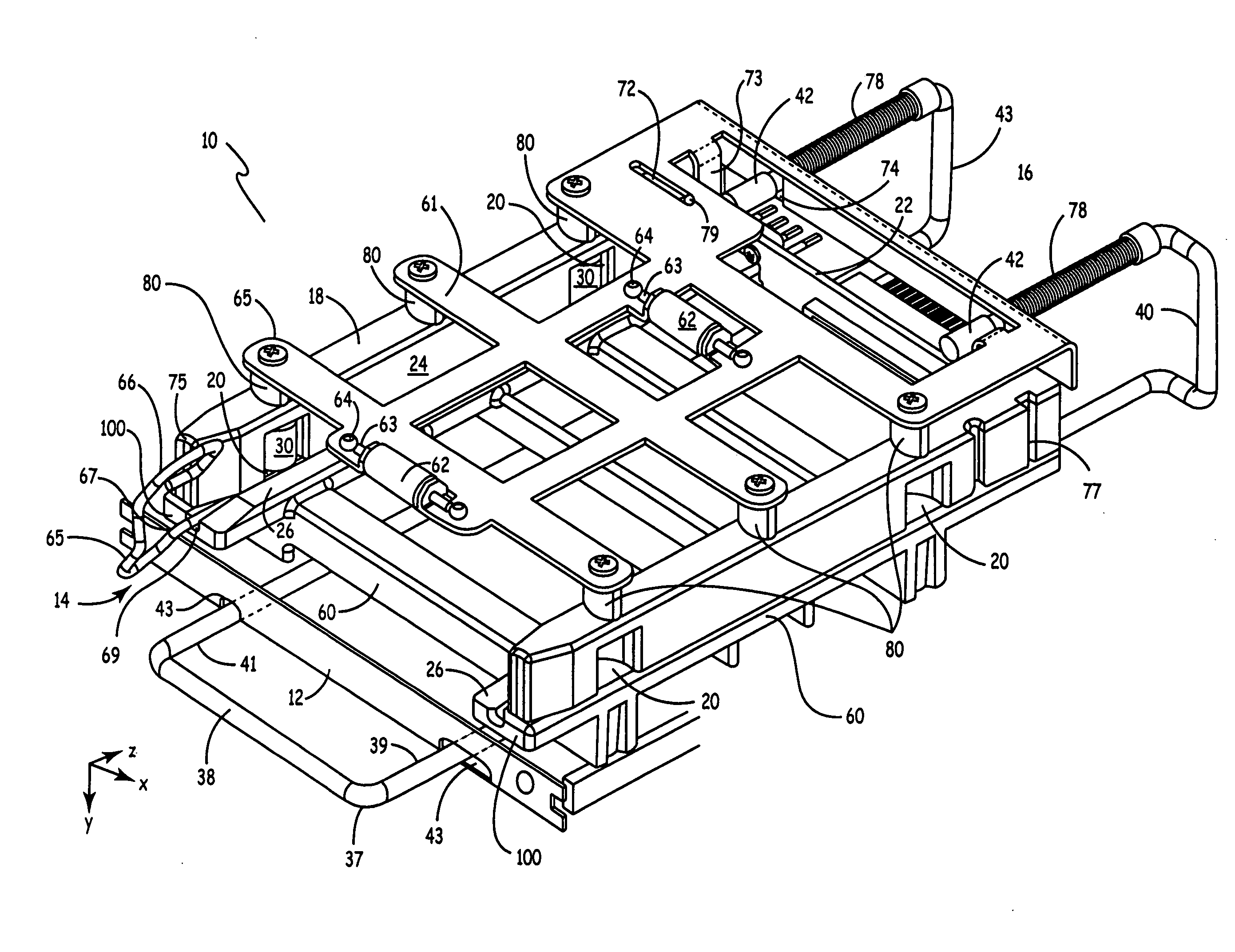
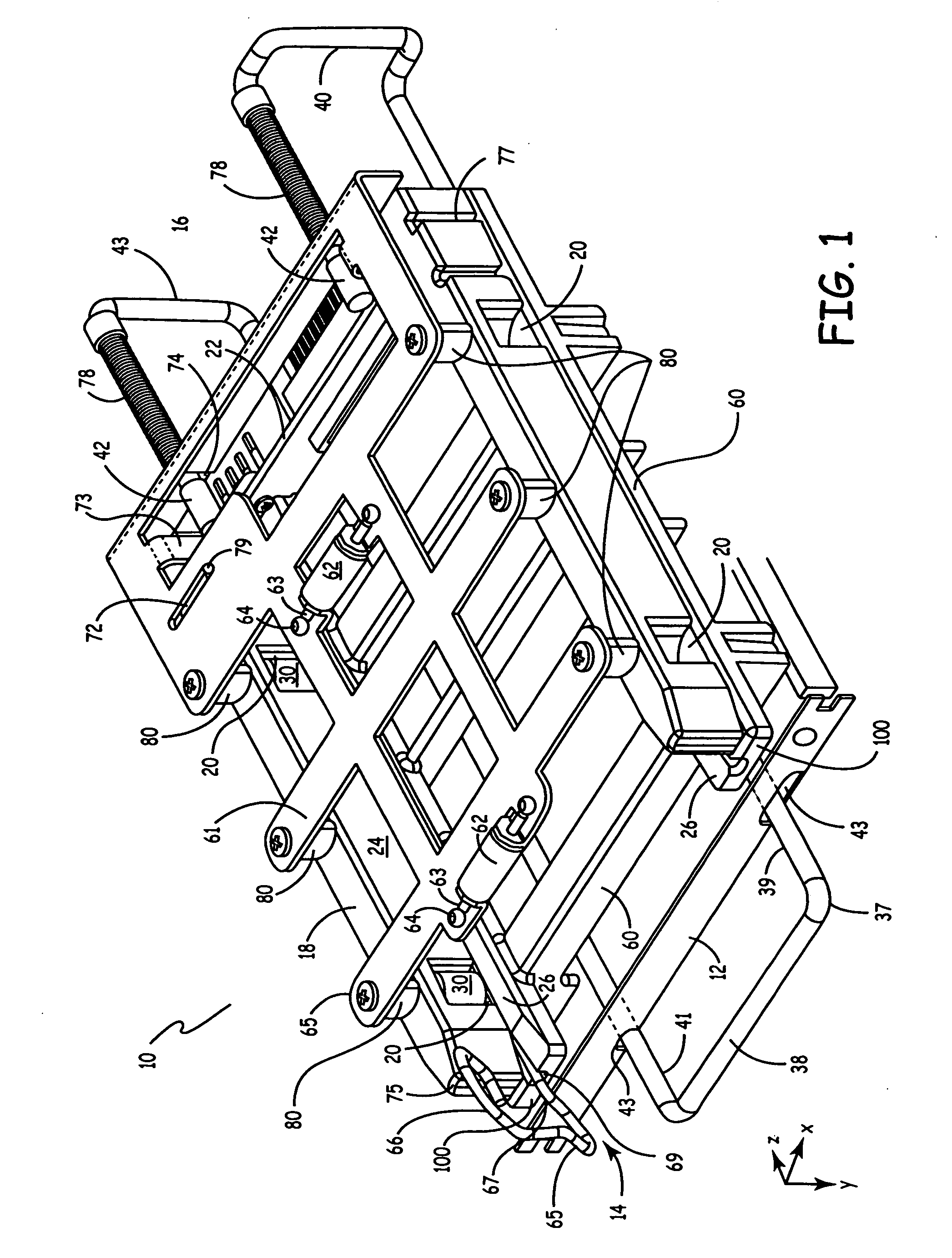
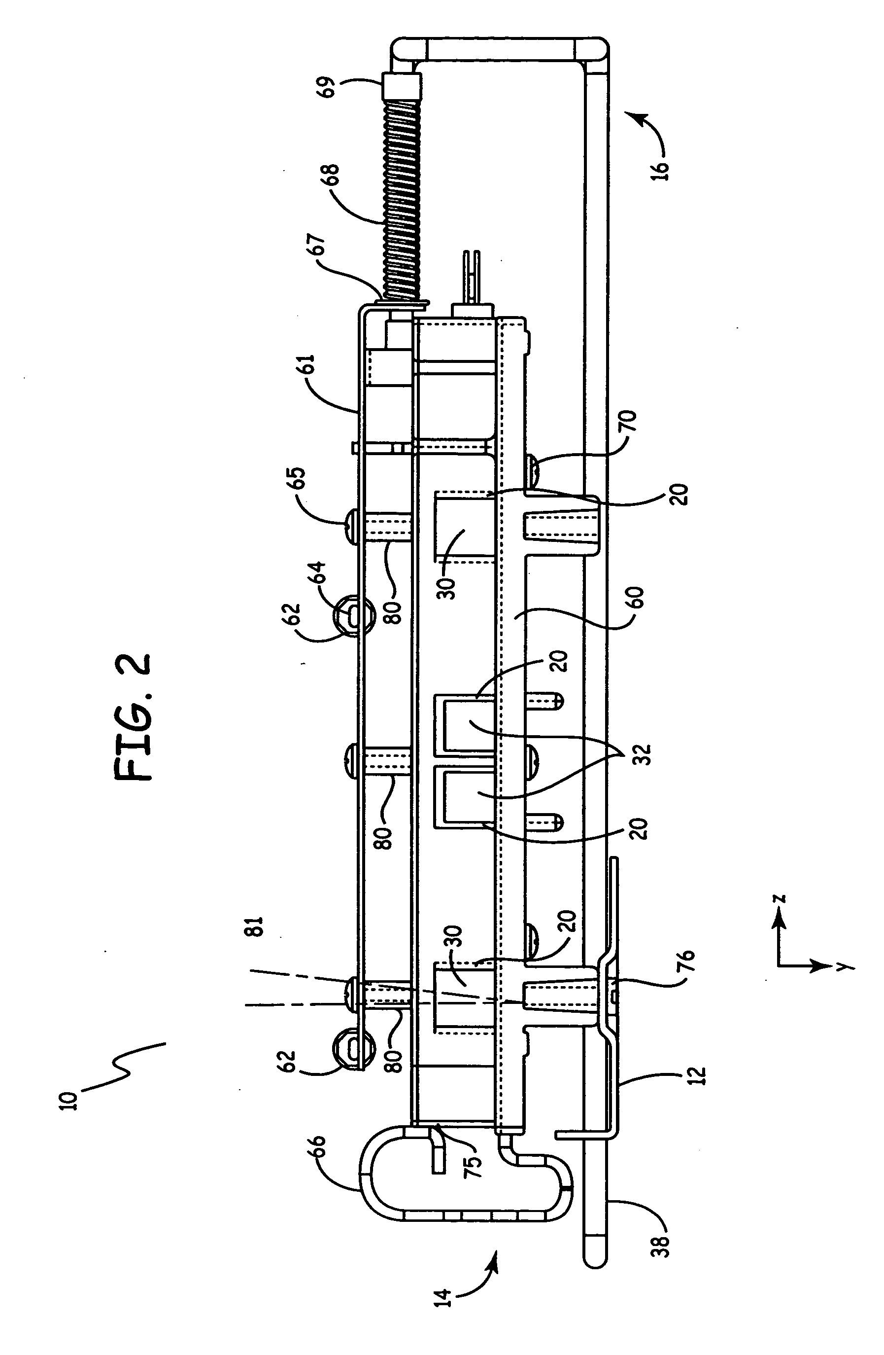
  • Hard drive test fixture
  • Hard drive test fixture
  • Hard drive test fixture

Examples


example 1

[0057] Methods and Materials

[0058] Test fixtures of the present invention were tested in the following manner. Three test conditions were created.

[0059] First, 10 drives manufactured by Western Digital were tested in a test fixture of the present invention that was placed on a pallet placed on a bench (“Pallet Fixture”).

[0060] Second, drives were tested in a test fixture of the present invention that was placed in an environmental testing chamber (“Chamber Fixture”). The tests were performed on 10 drives manufactured by Western Digital. The drives were distributed in a chamber that was fully populated with 90 drives. The 10 drives were distributed amongst the 90 total drives in the chamber such that the 10 drives formed a oval pattern. The remaining 80 untested drives were operating in maximum stroke maximum velocity mode, thus creating the maximum amount of vibration possible under the testing conditions.

[0061] Third, for comparison, 10 drives manufactured by Western Digital we...


PUM

PropertyMeasurementUnit
angleaaaaaaaaaa
vibration dampingaaaaaaaaaa
thermal testingaaaaaaaaaa

Abstract

The present invention is a method and apparatus for testing electrical or optical devices. The invention includes a test fixture having a base component, a first rail and a second rail coupled to the base component, a top component coupled to the first and second rails, and an interposer coupled to the first and second rails.

Description

CROSS-REFERENCE TO RELATED APPLICATION(S) [0001] None. FIELD OF THE INVENTION [0002] The present invention relates generally to a fixture or carrier for securing and testing an electrical or optical device. In a specific example, the present invention relates to a fixture for securing and testing a hard drive. BACKGROUND OF THE INVENTION [0003] Computer hard drives are generally subjected to a “burn-in” testing procedure. Further, the drives are also usually subjected to thermal testing or environmental conditioning testing during the design and prototyping phases of the manufacturing process. A drive is typically held in a fixture or a carrier while it undergoes the burn-in or final verification testing procedures. Further, the fixture or carrier holding the drive may be placed in an environmentally-controlled test chamber for the testing procedures. These chambers are designed to expose the device under test to controlled temperature and humidity levels so that the drive manufactu...

Claims


Application Information

Patent Timeline
Patent Type & Authority Applications(United States)
IPC IPC(8): G01M99/00G01N19/00G11B25/04G11B33/12
CPCG11B33/121G11B25/043
Inventor WANEK, DONALDSANDS, RICHARDWALTER, ROBERTTROUTMAN, MARK
Owner BENCHMARK ELECTRONICS SUZHOU
Why Eureka
Try Eureka