Worktable elevating device for a planer

a technology of a planing table and an elevating device, which is applied in the direction of woodworking apparatus, manufacturing tools, flat surface machines, etc., can solve the problems of wasting labor and time, inability to quickly elevate a planing table, and complicated structure, and achieve the effect of quick movement of the worktabl

Inactive Publication Date: 2005-05-26
CHUANG BOR YANN
View PDF3 Cites 15 Cited by
  • Summary
  • Abstract
  • Description
  • Claims
  • Application Information

AI Technical Summary

Benefits of technology

[0005] The objective of this invention is to offer a worktable-elevating device for a planer, able to quickly move the worktable up and down by pulling a control rod and automatically actuate the worktable to atop moving by releasing the control rod.

Problems solved by technology

A conventional planer usually has its worktable moved up and down by manually turning around a hand wheel, wasting labor and time and unable to quickly elevate a planing table.
Another conventional planer is provided with an electrically elevating device to drive a planing table to move up and down, having complicated structure and increasing producing cost.

Method used


Image

  • Worktable elevating device for a planer
  • Worktable elevating device for a planer
  • Worktable elevating device for a planer

Examples


Embodiment Construction

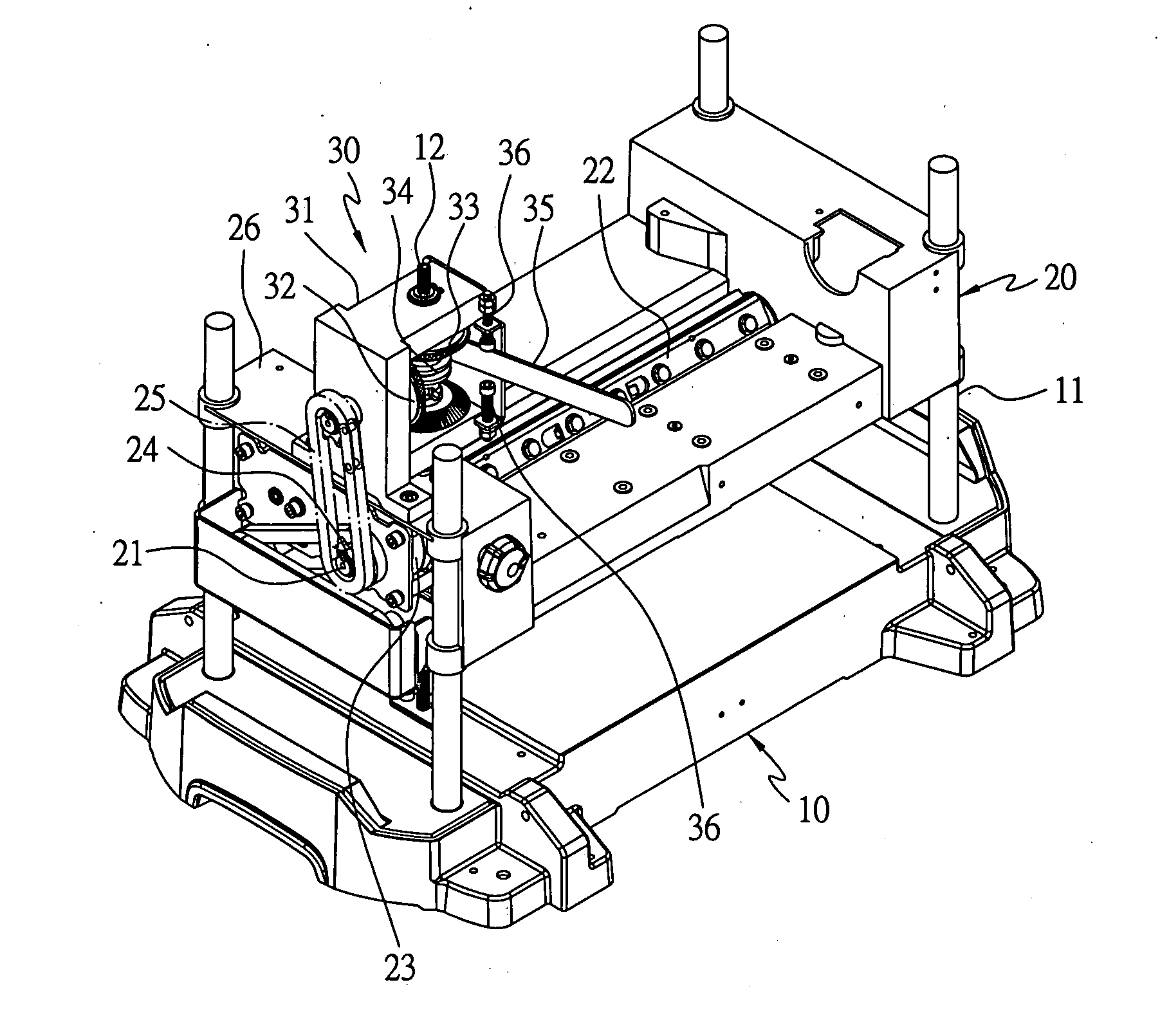
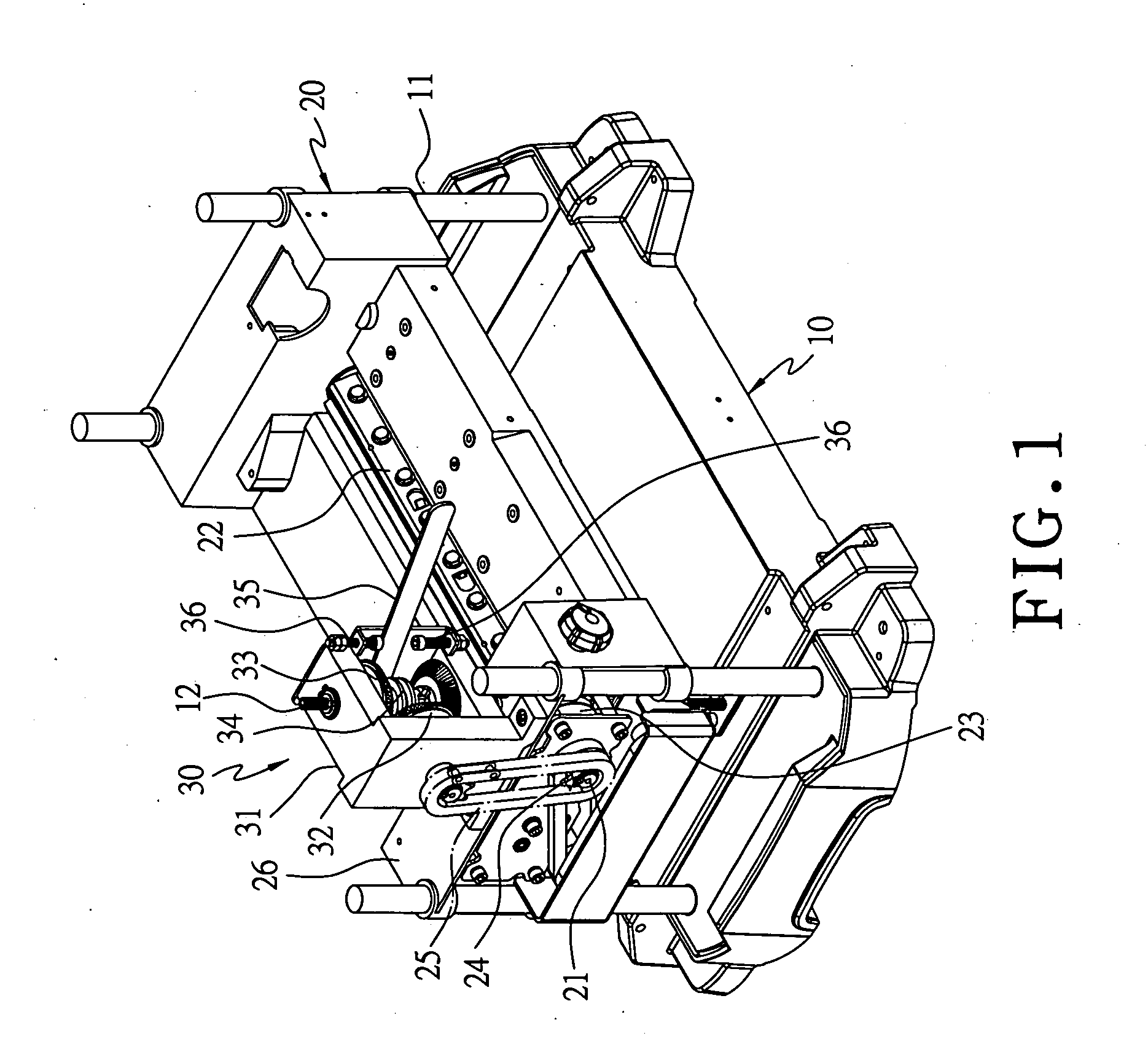
[0017] A preferred embodiment of a worktable elevating device for a planer in the present invention, as shown in FIGS. 1, 2 and 3, is combined with a bottom base 10, a planing table 20 of a planer.

[0018] The bottom base 10 has its four corners respectively fixed with a guide column 11 and has a worm 12 secured at a preset location on one side.

[0019] The worktable 20 is slidably fitted on the four guide columns 11 of the bottom base 10 and threadably assembled with the worm 12 of the bottom base 10, able to be moved up and down. The worktable 20 is provided with an actuating shaft 21 on a preset side, a knife shaft 22 for planing and a motor 23 for driving the actuating shaft 21 and the knife shaft 20. The actuating shaft 21 is provided with an actuating chain wheel 24 having an endless chain 25 engaged thereon.

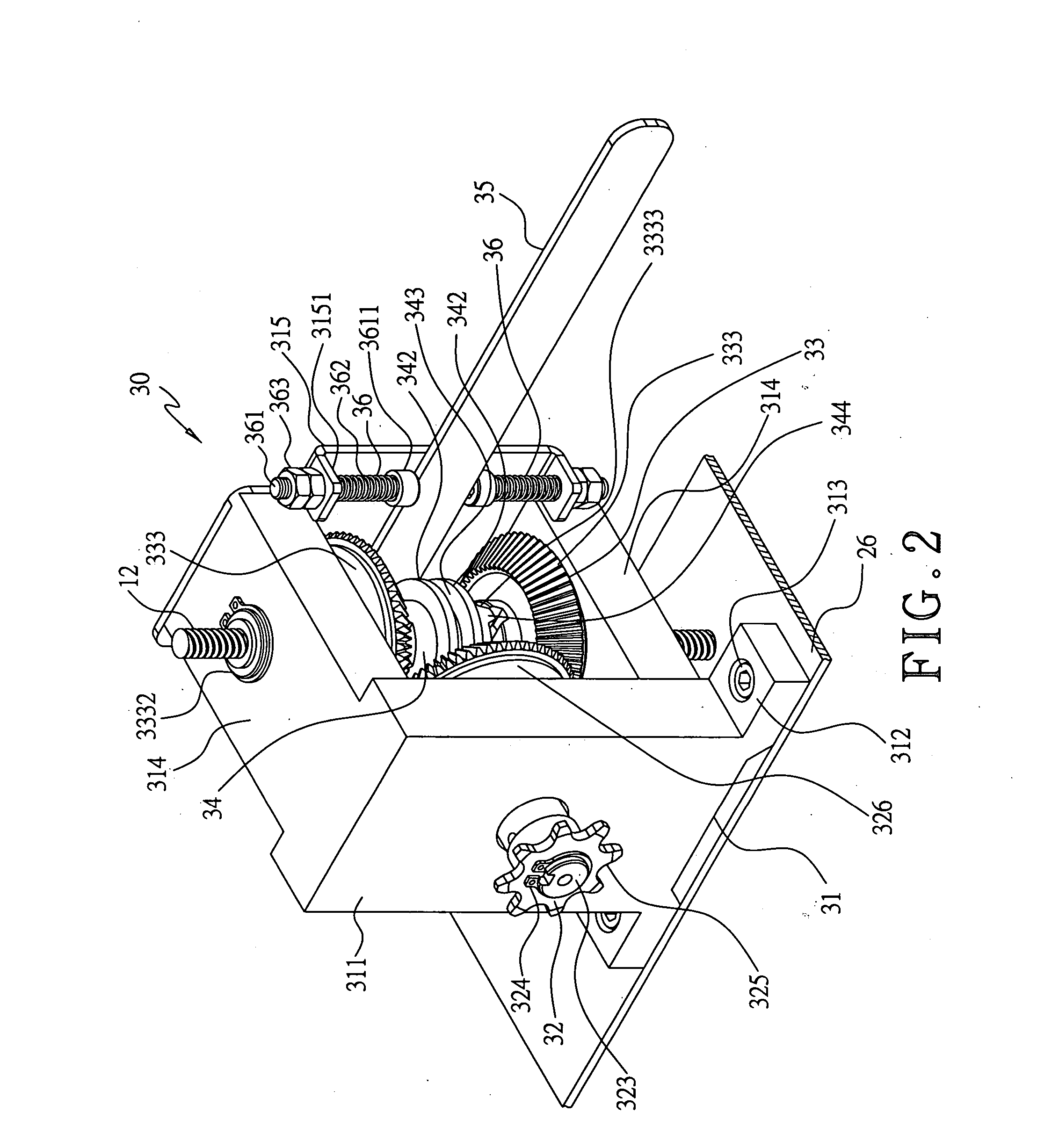
[0020] The worktable-elevating device 30, as shown in FIGS. 3, 4 and 5, includes a base body 31, an input gear unit 32, two output gear unit 33, a worm holder 34, a control...


PUM


Abstract

A worktable-elevating device for a planer is assembled on a worktable, including a base body provided with an input gear unit, two output gear units; a control rod, two elastic compressing units, and a worm holder. The input gear unit is driven by a motor installed on the worktable to rotate and actuate the two output gear units to rotate reversely. The control rod is pulled upward or downward to make the worm holder mesh with one of the two output gear units. As the worm holder and the planing table are screwed on the worm of the base body; therefore when the worm holder is driven to move upward or downward, the worktable will synchronously be moved up or down quickly. When the control rod is released and automatically recovers its original position by the elastic compressing units, the worktable will stop moving up and down.

Description

BACKGROUND OF THE INVENTION [0001] 1. Field of the Invention [0002] This invention relates to a worktable-elevating device for the planing table of a planer, particularly to one able to move the worktable up and down with quickness. [0003] 2. Description of the Prior Art [0004] A conventional planer usually has its worktable moved up and down by manually turning around a hand wheel, wasting labor and time and unable to quickly elevate a planing table. Another conventional planer is provided with an electrically elevating device to drive a planing table to move up and down, having complicated structure and increasing producing cost. SUMMARY OF THE INVENTION [0005] The objective of this invention is to offer a worktable-elevating device for a planer, able to quickly move the worktable up and down by pulling a control rod and automatically actuate the worktable to atop moving by releasing the control rod.BRIEF DESCRIPTION OF DRAWINGS [0006] This invention will be better understood by r...

Claims


Application Information

Patent Timeline
Patent Type & Authority Applications(United States)
IPC IPC(8): B27C1/04B27C1/14
CPCB27C1/14B27C1/04
Inventor CHUANG, BOR YANN
Owner CHUANG BOR YANN
Why Eureka
Try Eureka