Grooved single facer belt

Inactive Publication Date: 2005-05-26
ALBANY INT CORP
View PDF15 Cites 15 Cited by
  • Summary
  • Abstract
  • Description
  • Claims
  • Application Information

AI Technical Summary

Benefits of technology

[0012] It is a further object of the present invention to provide a belt with improved release chara

Problems solved by technology

The belt experiences severe operating conditions.
Moreover, the belt must be flexible yet have lengthwise strength and widthwise rigidity sufficient to withstand wrinkling, which may cause the belt to drift undesirably from side to side.
Still further, the belt faces two opposing problems.
Although both of these solutions increase the coefficient of fric

Method used


Image

  • Grooved single facer belt
  • Grooved single facer belt
  • Grooved single facer belt

Examples


Example

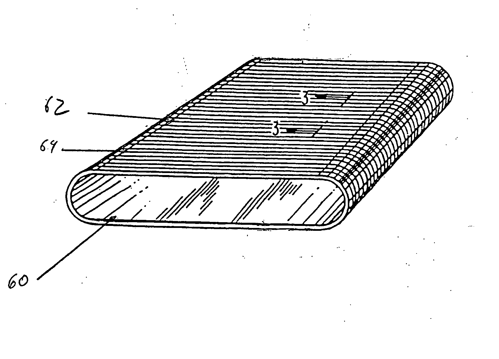
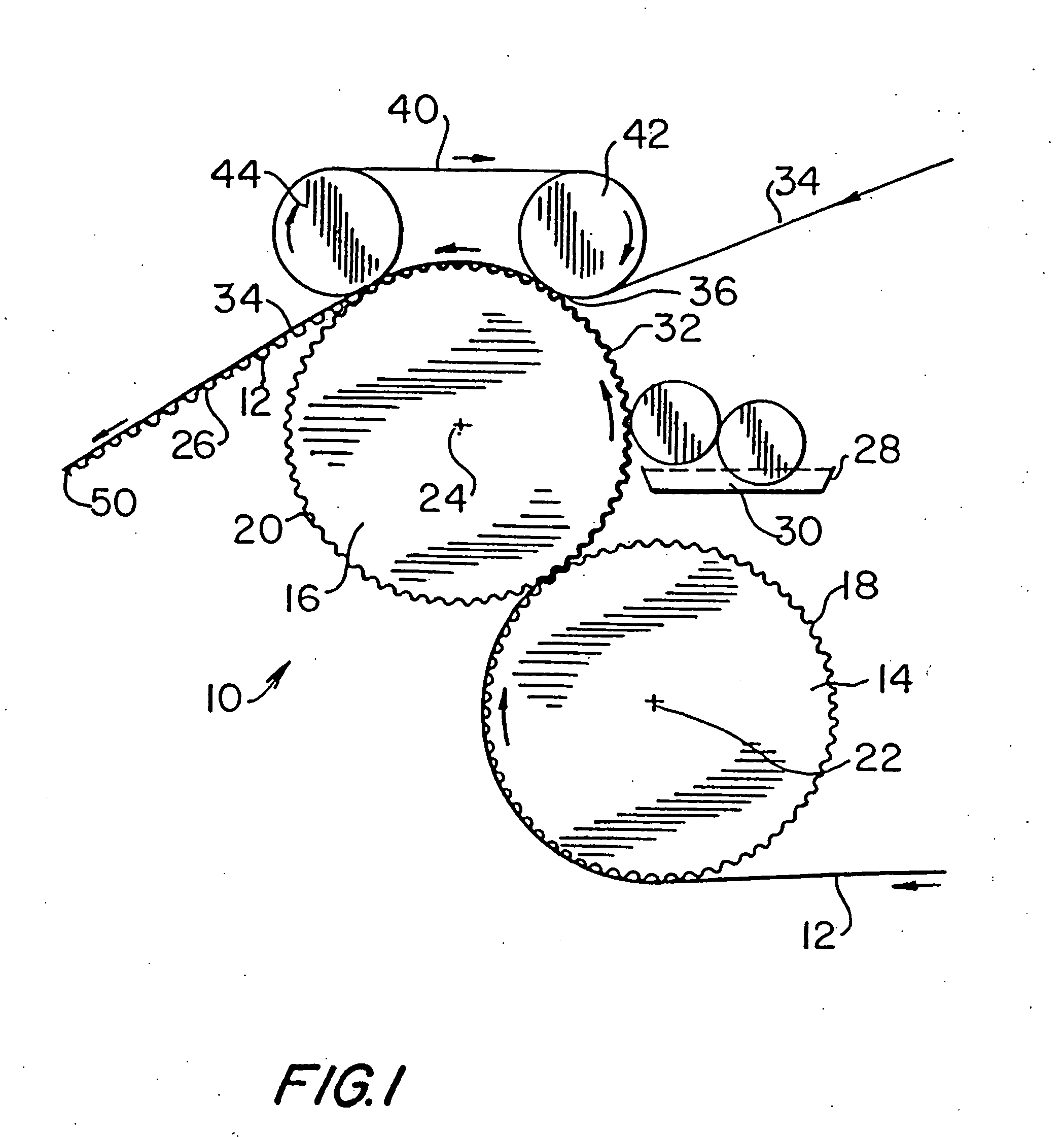
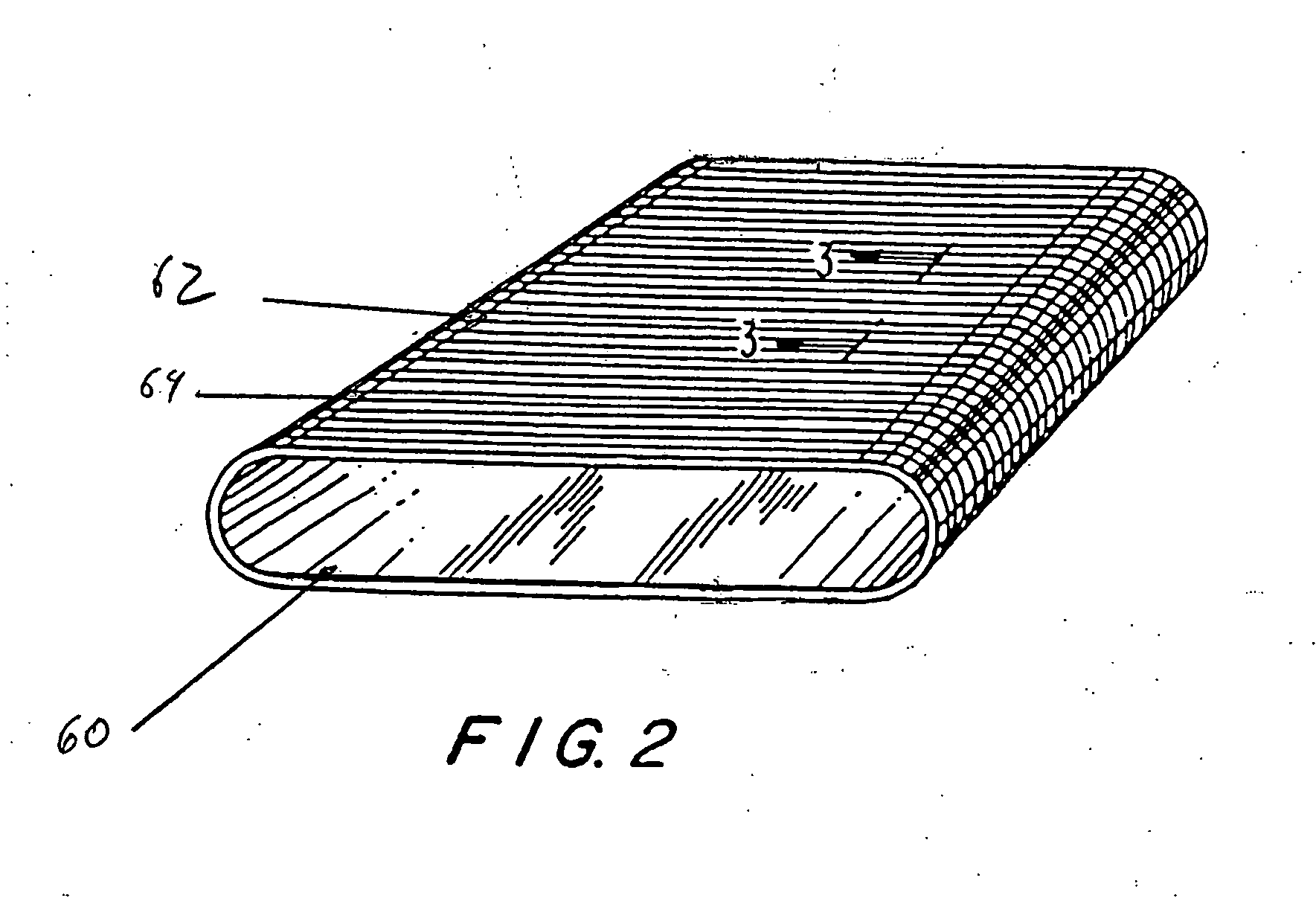
[0025] Turning now to these figures, FIG. 1 is a schematic view of a typical belted single-facer section 10 of a corrugated board production line. A core paper 12, previously exposed to steam, which makes it more pliable, is fed continuously between a pair of cooperating rolls 14, 16. The rolls 14,16 have uniformly spaced, peripheral teeth 18, 20, which mesh as the rolls 14, 16 rotate about their respective, parallel axes 22, 24. The meshing teeth 18, 20 produce corrugations 26 in the core paper 12.

[0026] A coating mechanism 28 applies a starch paste 30 to the crests 32 of the corrugations 26 in the core paper 12.

[0027] The corrugated core paper 12 is continuously applied to a liner paper 34 at point 36, where a belt 40, which is trained around a pair of spaced rollers 42, 44, passes around roller 42. The spaced rollers 42, 44 are so disposed that belt 40 bears against roll 16, and both may form nips with roll 16, so that the belt 40, trained thereabout, bears against roll 16 for ...


PUM

PropertyMeasurementUnit
Permeabilityaaaaaaaaaa
Polymericaaaaaaaaaa

Abstract

The present invention relates to a single facer corrugator belt having a base structure. The base structure includes an inside and an outside surface and a machine or running direction and a cross machine direction. The base structure is formed by machine direction yarns and cross machine direction yarns and has grooves formed in a surface of the base structure. Alternatively, the corrugator belt may include includes holes formed in a surface of the base structure.

Description

BACKGROUND OF THE INVENTION [0001] 1. Field of the Invention [0002] The present invention relates to corrugated paper board manufacture and to the belts required by the machines used to manufacture that variety of paper board. More specifically, the present invention relates to the belts that may be used on the single-facer section of a corrugated board production line. [0003] 2. Description of the Prior Art [0004] In the manufacture of corrugated paper board, a so-called core paper is heated by steam, which makes it more pliable, and is then fed into a nip formed between a pair of toothed rollers whose teeth mesh, thereby corrugating the core paper in a uniform, undulating pattern. Starch paste is subsequently applied to the crests of the corrugated core paper, which is then mated to a liner paper in a press nip. There, the corrugated core paper and liner paper are bonded together to form a completed sheet, which can then be further processed as desired. [0005] In one machine used ...

Claims


Application Information

Patent Timeline
IPC IPC(8): B31F1/28
CPCY10T428/2457B31F1/2877
Inventor BILLINGS, ALAN L.ZILKER, GREGORY
Owner ALBANY INT CORP
Why Eureka
Try Eureka